VI User Manual.pdf - 第237页
Tools library Vision 2007 4.10 User Manua l Rev 01 7 - 75 7.12.3.2 .tst file configuration To define use of the external camera for Data M atrix decoding open the Test file configuration window. These parameter s are onl…
Tools library
7 - 74 Vision 2007 4.10 User Manual Rev 01
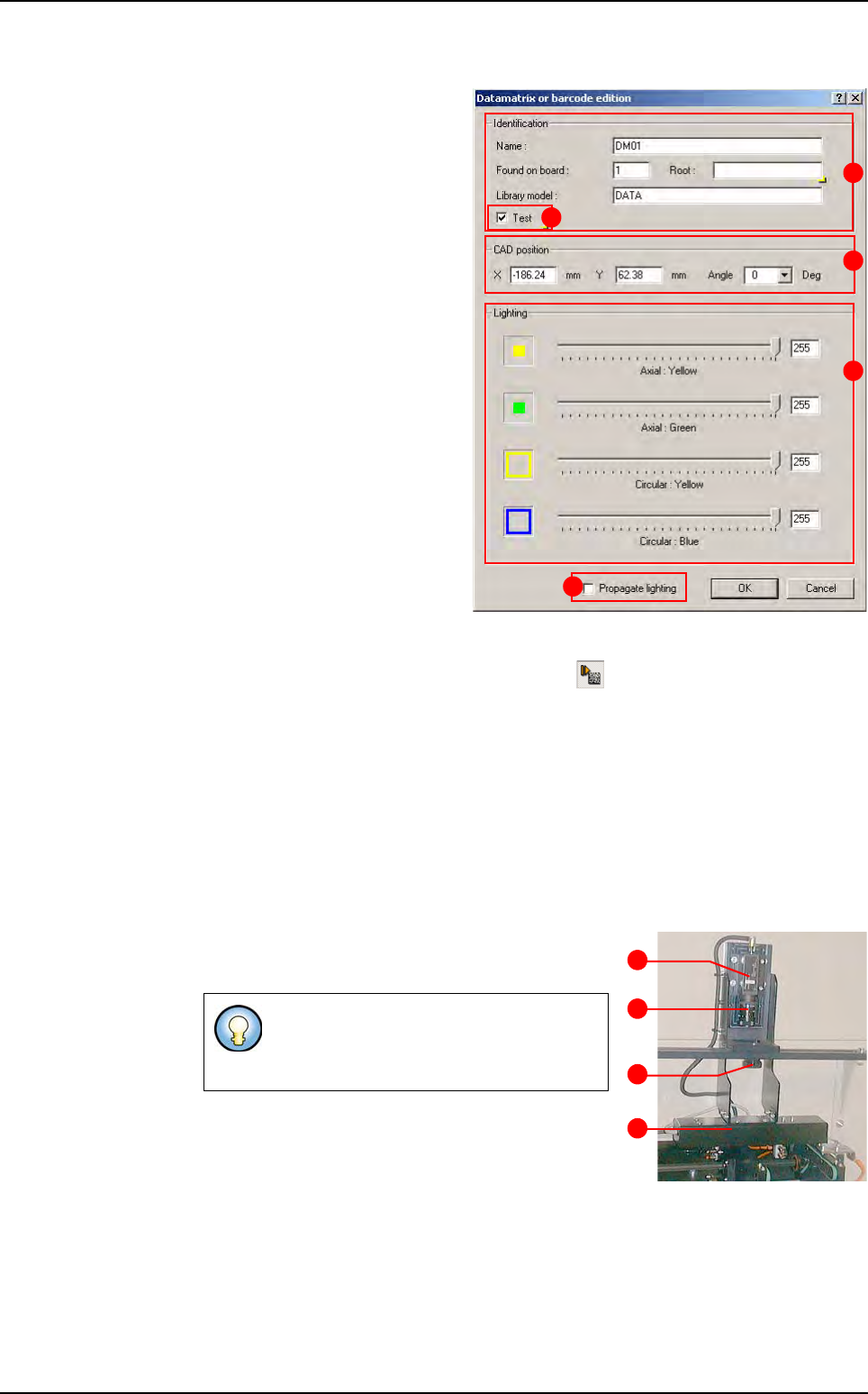
7.12.2.2 Data Matrix CAD edition
When you click on a Data Matrix
in the CAD representation, the
Data Matrix edition window ap-
pears.
In
Identification (A) section, ap-
pear the reference designator,
board number, and library mod-
el. The root is the 1st characters
that should be decoded by the
Data Matrix tool.
In
CAD position (B) section,
position and angle of the Data
Matrix are displayed.
In
Lighting (C) section, use the
cursors to adjust the ligthing.
Tick
Test (D) conditions.
Tick
Propagate lighting (E) to
propagate the lighting for all
Data Matrix.
7.12.2.3 Data Matrix execution
Click on the Execute internal data matrix icon in the Execution tools bar. When
the Data Matrix pass, the decoded string is displayed in the console.
7.12.3 Data Matrix using an external camera
The external Data Matrix inspection uses an external camera that is able to take picture dur-
ing the board loading. This camera, Sony XC_55, supply images to the Cognex Data Matrix
tool, which read the code before board stopping.
This option does not take time but you can only read one Data Matrix per panel.
7.12.3.1 Hardware description
A
Sony XC_55 camera,
B 50 mm lens,
C Fastening screw,
D White lighting.
You can adjust the focus with focus ring
and the picture brightness with the dia-
phragm.
A
B
C
D
E
A
B
C
D
Data Matrix
Tools library
Vision 2007 4.10 User Manual Rev 01 7 - 75
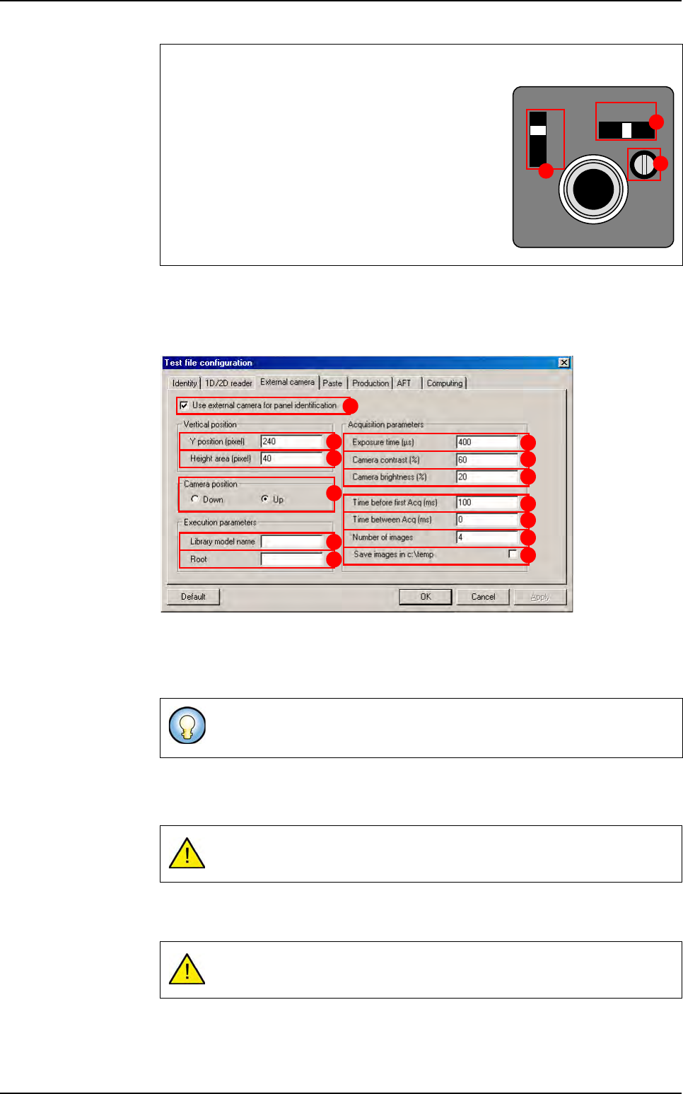
7.12.3.2 .tst file configuration
To define use of the external camera for Data Matrix decoding open the Test file
configuration
window. These parameters are only dedicated to one .tst file.
Tick
Use external camera for panel identification (A).
Y position (pixel) (B) determine the Data Matrix centre position in the picture.
Height area (pixel) (C) determine the Data Matrix height.
In
Camera position (D) section, choose which camera is used: top or bottom.
Enter the Data Matrix
Library model name (E) you want to use to detect Data Matrix.
Root (F) of Data Matrix used during production run. If the Data Matrix red has not the
same root, Vision 2007 will display a root error.
Exposure time (µs) (G) is the exposition time of the camera. If your picture is too
blur you will have to reduce it.
You can change the
Camera contrast (H) and the Camera brightness ( I ).
Camera settings
A The Signal switch must be in the 1N position.
B The Gain switch can be in the F or M position:
F is the fixed gain.
M is the manual gain, you can adjust it with the
Manual gain control volume (
C) if your picture is
too bright or too dark.
These 2 parameters will be used to cut the camera image so the processing
time is reduced.
If the
Library model name field is empty, there will be no inspection.
If the
Root field is empty we do not check Data Matrix root.
SIGNAL
A F M
GAIN
VIDEO OUT/DC IN/SYNC
1N
1 l
A
B
C
A
B
C
D
E
F
G
H
I
J
K
L
M
Data Matrix
Tools library
7 - 76 Vision 2007 4.10 User Manual Rev 01
Time before first Acq (ms) (J) is a delay between the SMEMA acknowledge (when
board go in the machine) and the first acquisition.
Time between Acq (ms) (K) is a delay between 2 pictures.
Number of images (L) to take (maximum 20).
Tick
Save image in C:\temp (M), if you want to save pictures during Data Matrix in-
spection.
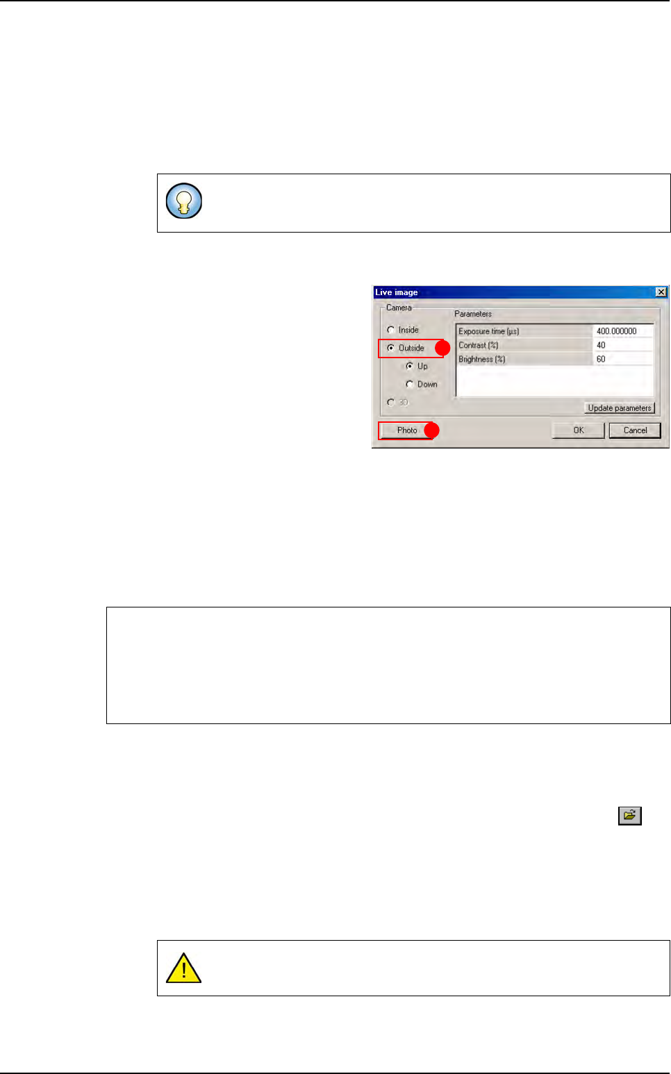
7.12.4 Maintenance mode
In Maintenance mode, press Video ac-
quisition
button, the Live image window
appears.
If you select
Outside (A), you can see a
live image from the camera used to read
the Data Matrix. You can choose
Up or
Down because there is an option to read
data matrix on the both side of a board.
The
Photo (B) button take an image with
the selected camera. The picture is saved
in
C:\vit\data folder and named:
Cam1.bmp if you have selected Inside camera,
Data Matrix.bmp for the outside camera,
3D.bmp for the 3D camera (3D option only).
It is helpful to store a good quality image of your Data Matrix because you will need it in library
to learn your Data Matrix type to the system.
7.12.5 Cognex Data Matrix model creation
7.12.5.1 Model description tab
1.
On the Model description tab, in the Edit a model window, click on the but-
ton. The .bmp file name to add in picture list window appears.
2. Select the image on which load the treatment.
3. Click on Edit area button to define the component size.
4. Choose the treatment operation: a new DMatrix tab appears behind the Model
description
tab.
Use this option to set and adjust the acquisition parameters. When your set-
tings are OK, you can remove the check box to save time.
If you have a poor quality picture you can:
Adjust the camera settings.
Tune the diaphragm and focus ring of the lens.
Tune the camera gain potentiometer in manual mode.
Be sure to select DM icon in the model description window.
A
B
Data Matrix