VI User Manual.pdf - 第280页
2D solder paste inspection 9 - 2 Vision 2007 4.10 User Manual Re v 01 3. In Position file na me ( C ), show the address of the gerbe r file. 4. The Board ( D ) section allows an offset betwee n the gerber mask and th e p…
Vision 2007 4.10 User Manual Rev 01 9 - 1
Chapter 9
2D solder paste inspection
To inspect solder paste, you need the screen printing mask drilling file. The files that Vision 2007 can import
are extended gerber type files (standard R274X).
9.1 Gerber file
9.1.1 Basics
During gerber importation, Vision 2007 extracts the position and surface of each paste pad and
represents it in the .tst file.
9.1.2 Import
In the Test file menu go to Import sub menu and select Gerber file to import the gerber file to
an existing .tst file for your panel.
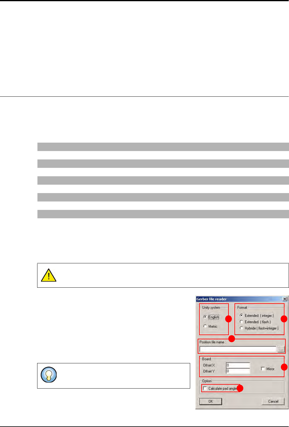
After selecting the previous menu, the Gerber file reader
window appears.
1. Choose the Unity system (A).
2. Choose the importation Format (B) of the gerber file:
Integer: all the elements even flash are imported as in-
teger (area calculated by sampling).
Flash: import only the flash elements.
Hybrid: this format combines the 2 importation formats.
The flash elements are imported as Flash format and
the others as Integer format.
G04 Generated on UCAM* G04 defines the start of a comment line
%FSLAX23Y23*% Scale definition 2 figures before and 3 after the decimal point
%MOIN*% Definition of the unit in inches (MOMM for mm)
%ADD10C,0.00472*% Definition of the 0.472 inch circular 10 tool
%ADD13R,0.02362X0.02756*% Definition of the 2.362 x 2.756 inch rectangular 13 tool
G54D10* Tool change (take circular 10 tool)
X1622Y2336D02* Movement with the tool up
X1629Y2334D01* Movement with the tool down
X1780Y1931D03* Movement of the tool in flash (up/down movement of the tool)
The .tst file must at least have the fiducial position.
Import in Flash does not take long and gives an idea
of the final result rapidly.
A B
C
D
E
2D solder paste inspection
9 - 2 Vision 2007 4.10 User Manual Rev 01
3. In Position file name (C), show the address of the gerber file.
4. The Board (D) section allows an offset between the gerber mask and the panel.
5. Tick Calculate pad angle (E) to compute the pad angle. The pad angle is important if you
have, for example, component at 45° on your board. By default the pad angle is set at 0°. This
option make the gerber file importation longer.
6. Click OK to start importing.
9.1.3 Gerber offset adjustment
Overall movement of the gerber representation according to the required offset. Often, the refer-
ence point (0,0) of the gerber does not correspond to the .tst file (0,0), which is the lower edge
in contact with the machine stop.
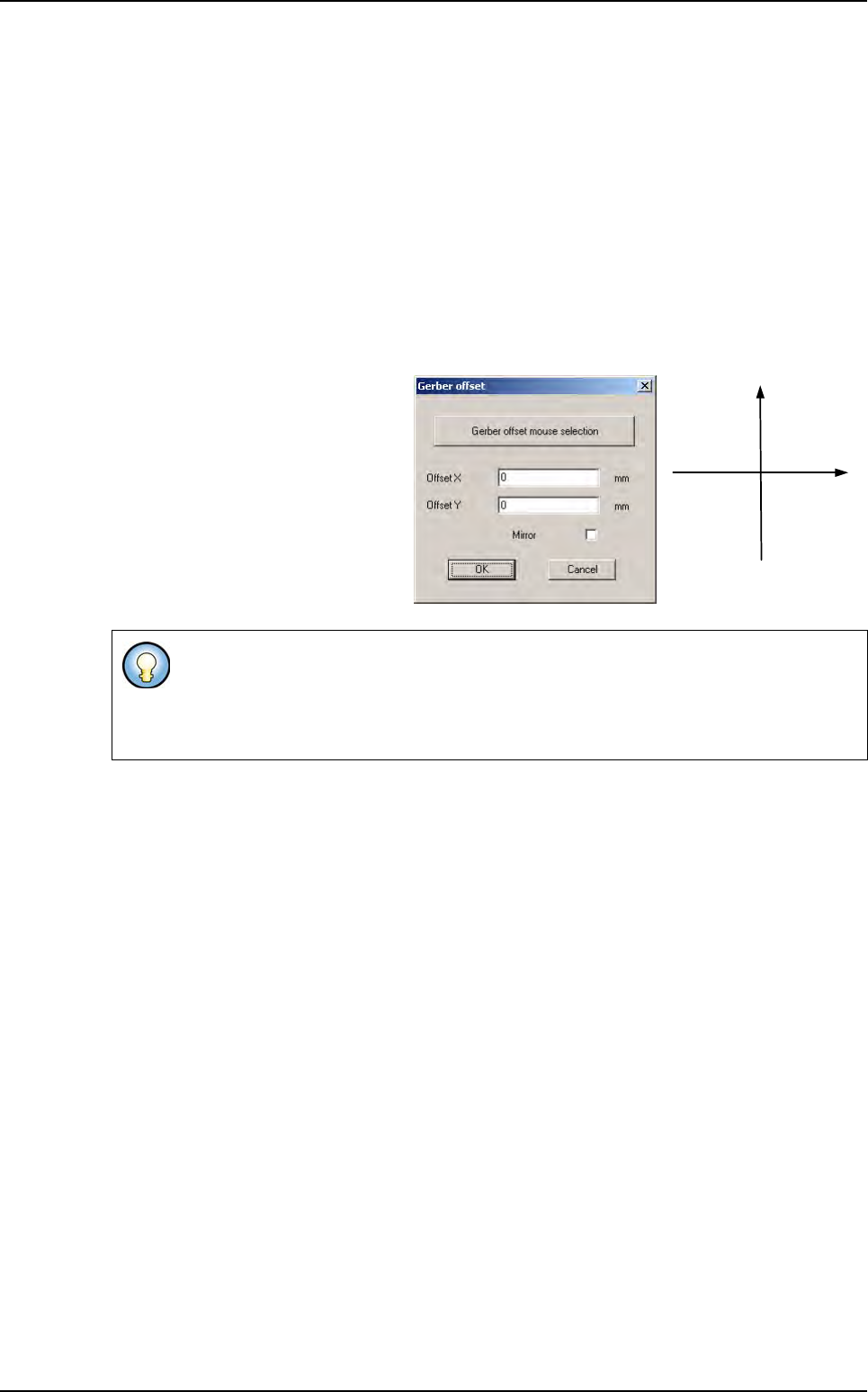
To adjust the reference point go to
the Test file menu and in the Import
sub menu select Gerber offset, the
next dialog box appears.
This dialog box enables all the paste
pads to be moved according to the
offset required, as well as a mirror to
be performed, as sometimes the ger-
ber file represents a view of the mask
from below.
If you know the exact offset between the gerber mask and the .tst file enter it directly
and click on OK to apply the offset.
If not, click on Gerber offset mouse selection to start the graphic selection of the pads
and the corresponding component (see next page).
- X + X
+ Y
- Y
Gerber file
2D solder paste inspection
Vision 2007 4.10 User Manual Rev 01 9 - 3
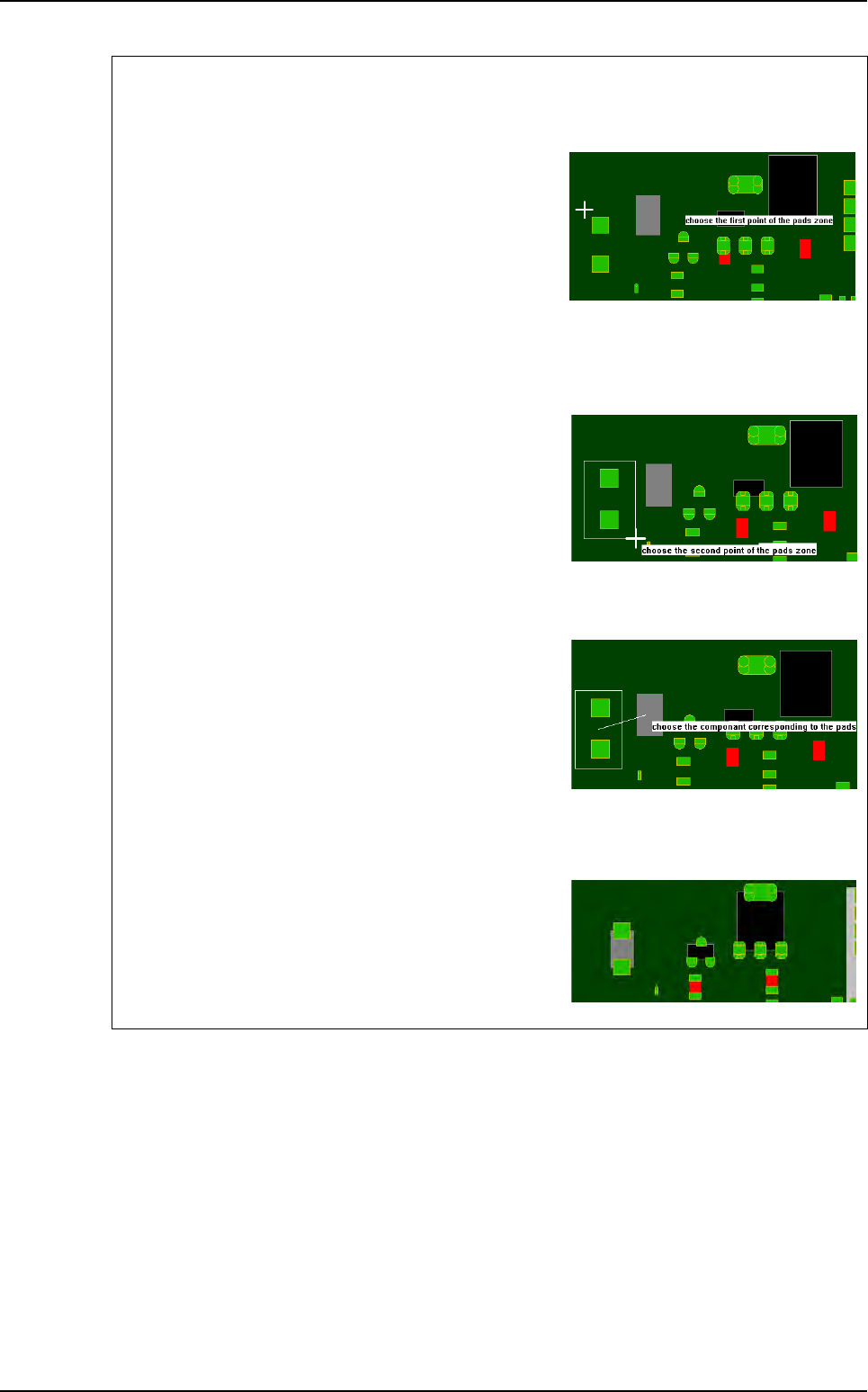
Graphic selection of the pads and the corresponding component
1st step
Click on the 1st point to describe the encompassing
rectangle of the pads group.
To exit the mode:
- During the pads group selection, select an empty rect-
angle.
- During the component selection, click outside of a compo-
nent.
2nd step
Click on the 2nd point to describe the encompassing
rectangle of the pads group.
You must still use offset to set gerber in view.
3rd step
Click on the component corresponding to the pads
group.
During the selection, you still can use the zoom and the
scroll bars.
Result
The software analyses the center of gravity of all the se-
lected pads and moves the gerber mask to make this
point coincide with the center of gravity of the selected
component.
Gerber file