VI User Manual.pdf - 第296页
Angle and distance calculation 10 - 2 Vision 2007 4.10 User Manual Rev 01 10.1 Text file definition: .mod file The file used for th e macro definition must have the extension .mod. The .mod file mu st have the same na me…
Angle and distance calculation
Vision 2007 4.10 User Manual Rev 01 10 - 1
Chapter 10
Angle and distance calculation
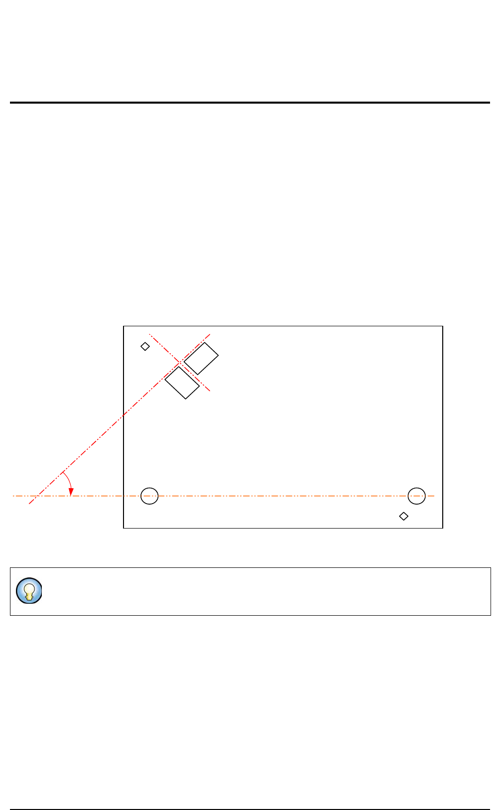
The Angle and distance calculation allows to verify that the distance and the angle measured between com-
ponents is within the tolerances.
You can check:
The distance in X direction between 2 components,
The distance in Y direction between 2 components,
The angle between 2 components,
The angle of a component when realigned with 2 others.
You define in a text file the distance and angle you want to measure. You specify the components reference
designators involved, the expected values and the tolerances.
If the text file is present the calculations are performed after the whole board inspection in Debug and in Pro-
duction mode as well.
Sensor 1 and sensor 2 must be at 90°.
Sensor 1 must be at 45° with the line made by 2 holes.
45° from
plane +/- .1
90° from the results
of Sensor 1
Fid 1
Sensor 1
Sensor 2
Mounting
hole 2
Mounting
hole 1
Fid 2
Plane (result from hole 1 and 2)
Angle and distance calculation
10 - 2 Vision 2007 4.10 User Manual Rev 01
10.1 Text file definition: .mod file
The file used for the macro definition must
have the extension .mod.
The .mod file must have the same name as
the .tst file and must be in the same directory.
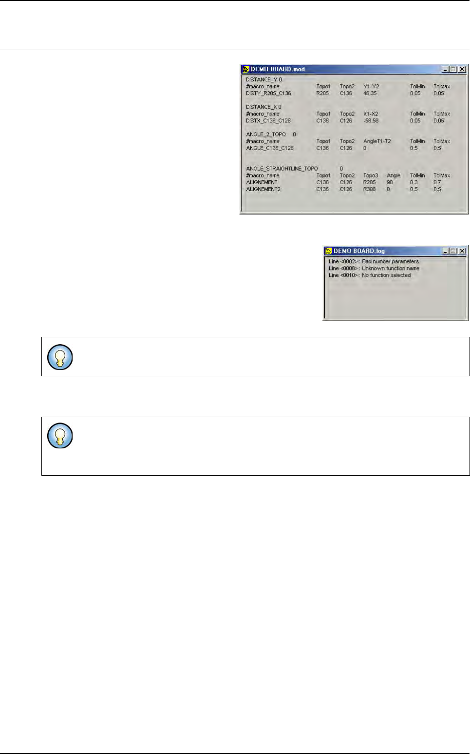
When opening a .tst file or starting production, the software looks for the .mod file and analyze it:
If some errors are detected in the .mod file, a .log file is created
and displayed with the list of the unknown lines.
If you change something in the .mod file, you must re-load the
.tst file to take the changes into account:
• In Debug mode: close and open again,
• In Production mode: exit and restart production.
The number of calculation for each function is not limited. The calculation will be executed only if the
involved components are tested.
Ctrl+E and Ctrl+B are not working on these functions.
If one component is in statistical monitoring, the function will be in statistic also (they are not
transfered to SPC LightHouse software).
If one component is missing the result of the function will be missing.
Angle and distance calculation
Vision 2007 4.10 User Manual Rev 01 10 - 3
10.2 Macros definition
10.2.1 Macro to check the distance between 2 components
DISTANCE_X: function to calculate the distance in X direction
ALIGNEMENT_X = X
TOPO1
-X
TOPO2
DISTANCE_Y: function to calculate the distance in Y direction
ALIGNEMENT_Y = Y
TOPO1
-Y
TOPO2
10.2.2 Macro to check the angle between 2 components
ANGLE_2_TOPO = T
TOPO1
-T
TOPO2
If <board number> = 0 we execute the function on all the boards of the panel.
The minimum and maximum tolerances can be asynchronous. (i.e.: - 0.100
and + 0.150).
DISTANCE_X <board number>
<result name> <TOPO1> <TOPO2> <expected value > <tolerance min> <tolerance max>
DISTANCE_Y <board number>
<result name> <TOPO1> <TOPO2> <expected value > <tolerance min> <tolerance max>
ANGLE_2_TOPO <board number>
<result name> <TOPO1> <TOPO2> <expected value > <tolerance min> <tolerance max>
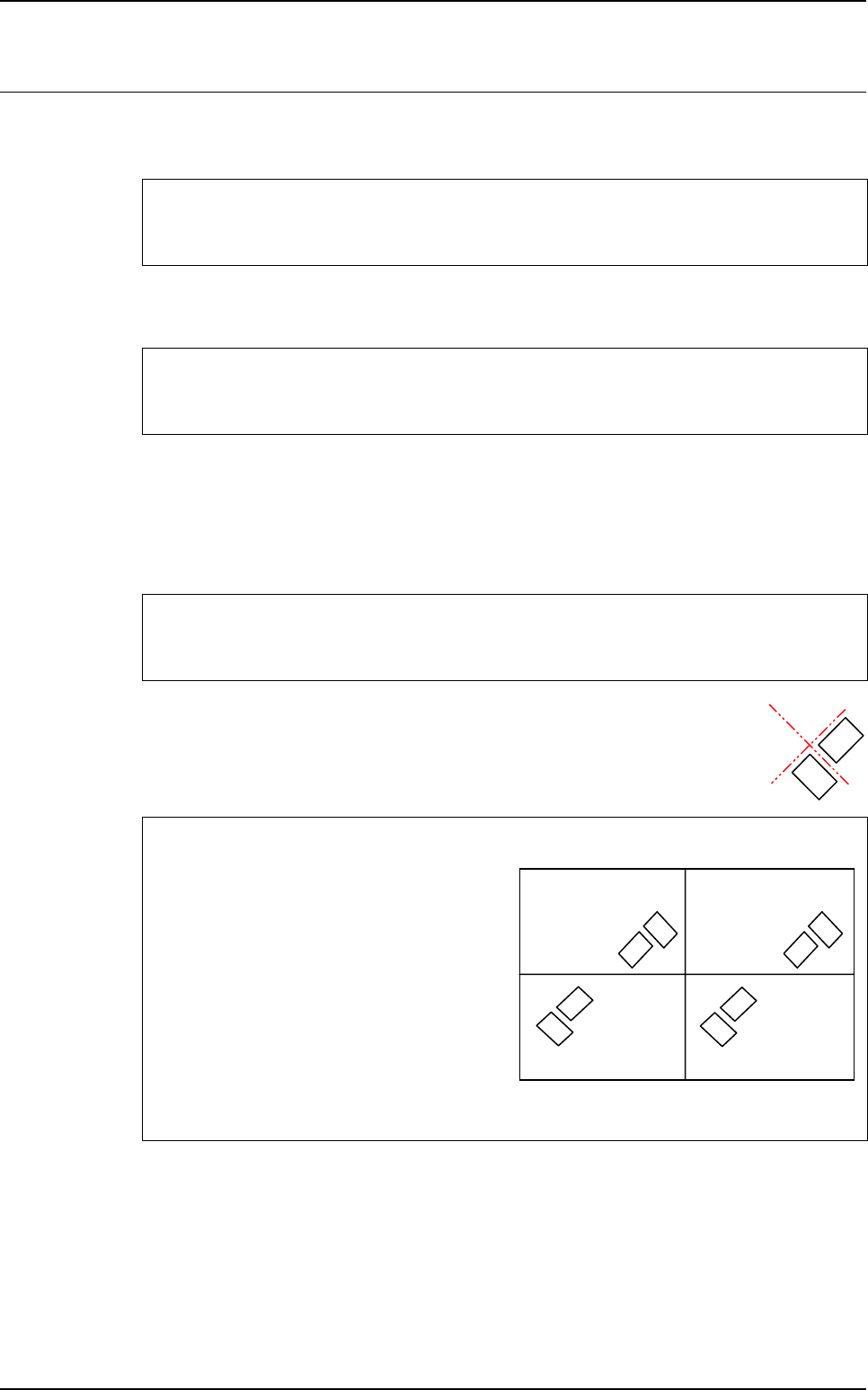
To know the expected value to enter in the .mod file
<expected value > = T
TOPO1
-T
TOPO2
In the .tst file:
• Board 1 & 3: T1 = 315° T2 = 45°
⇒
T1-T2 = 270°
• Board 2 & 4: T1 = 135° T2 = 225°
⇒
T1-T2 = - 90°
In the .mod file:
• ANGLE_2_TOPO 0
• SENSOR-ANGLE T1 T2 270 0.1 0.1
Board 1
at 0°
Board 3
at 0°
Board 2
at 180°
Board 4
at 180°
Topo1
Topo2
Topo1
Topo2
Topo1
Topo2
Topo1
Topo2