VI User Manual.pdf - 第299页
Angle and distance calculation Vision 2007 4.10 User Manua l Rev 01 10 - 5 To know the expected valu e to enter in the .mod file To calculate th e expected angle be tween a compo nent and a straight line, you need to kno…
Angle and distance calculation
10 - 4 Vision 2007 4.10 User Manual Rev 01
10.2.3 Macro to check the angle of 1 component and 1 line
Topo1 and Topo2 will determine the straight line, and the macro
ANGLE_STRAIGHTLINE_TOPO will return the angle between this line and Topo3.
ANGLE_STRAIGHTLINE_TOPO <board number>
<result name > <TOPO1> <TOPO2> <TOPO3> <expected value > <tolerance min>
<tolerance max>
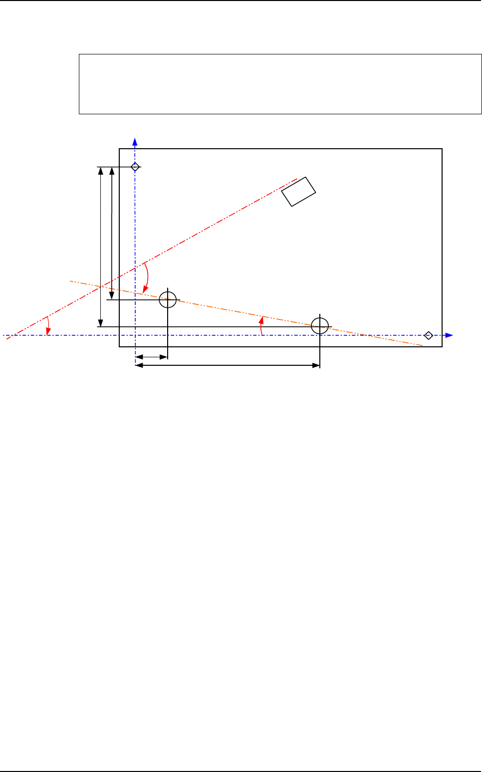
ρ
T
Topo3
θ ?
Fid 1
Topo2
Topo1
Fid 2
Y1
Y2
X2
X1
Macros definition
Angle and distance calculation
Vision 2007 4.10 User Manual Rev 01 10 - 5
To know the expected value to enter in the .mod file
To calculate the expected angle between a component and a straight line, you need to
know the orientation of this line in the orthonormal referential (fiducials referencial).
The variable a is the slope of the straight line made by Topo1 and Topo2 in the
orthonormal referential because the line equation is:
Y = aX + b
a =
ρ
is the theoretical angle of the straight line in the .tst file.
ρ
= ARCTAN (a)
• If a > 0
⇒
θ
= T3 -
ρ
• If a < 0
⇒
θ
= T3 +
ρ
The expected angle is different for boards with different orientations in the .tst file.
In the .tst file:
• Board 1 & 3:
T3 = 315°
ρ
= 0°
⇒
θ
= 315°
• Board 2 & 4:
T3 = 135°
ρ
= 0°
⇒
θ
= 135°
In the .mod file:
• ANGLE_STRAIGHTLINE_TOPO1
• ORIENTATION-SENSORT1T2T33150.10.1
• ANGLE_STRAIGHTLINE_TOPO2
• ORIENTATION-SENSORT1T2T31350.10.1
• ANGLE_STRAIGHTLINE_TOPO3
• ORIENTATION-SENSORT1T2T33150.10.1
• ANGLE_STRAIGHTLINE_TOPO4
• ORIENTATION-SENSORT1T2T31350.10.1
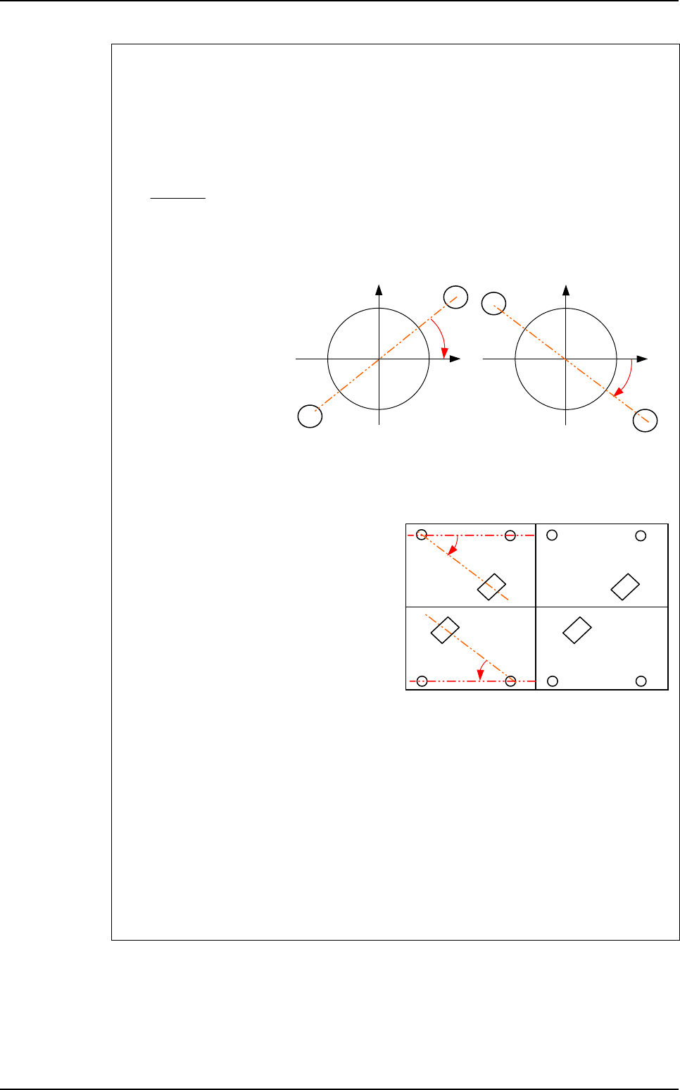
Y2 - Y1
X2 - X1
Topo2
Topo1
a < 0
1
1
X
Y
Topo2
Y
Topo1
a > 0
1
1
X
Board 1
at 0°
Board 3
at 0°
Board 2
at 180°
Board 4
at 180°
Topo3
Topo3
Topo2Topo1 Topo2Topo1
Topo1Topo2 Topo1Topo2
θ
θ
Topo3
Topo3
Macros definition
Angle and distance calculation
10 - 6 Vision 2007 4.10 User Manual Rev 01
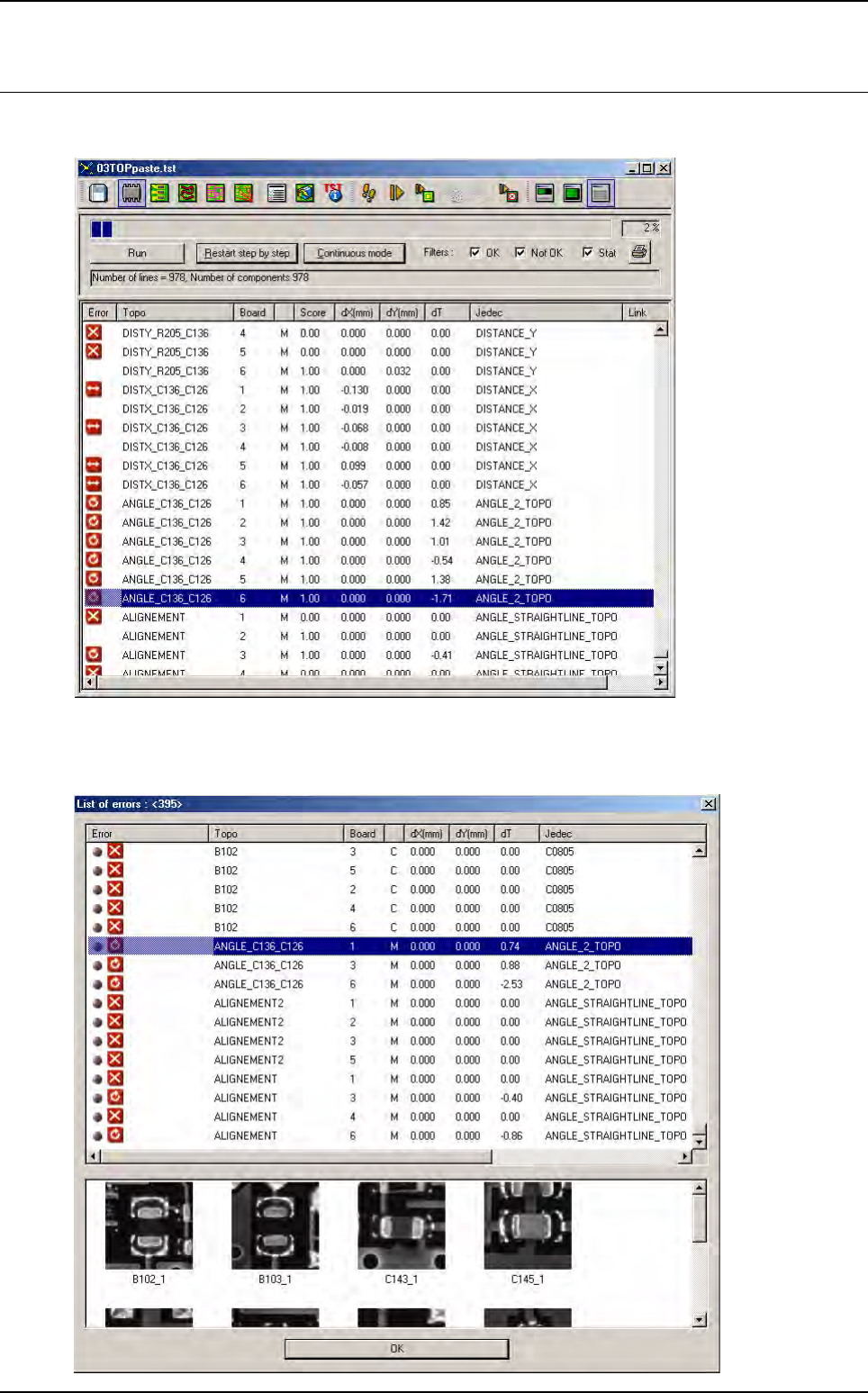
10.3 Results
In Debug mode, the results are displayed after all components have been inspected.
In Production mode, you can also see the results in the table chart. The macros are saved in the
database and also transferred to the repair station, but no images are taken for these error types.