VI User Manual.pdf - 第36页
Getting started 1 - 16 Vision2007 4.10 User Manu al Rev 01 Convert componen t to connector Convert selected component to connector. Convert component t o paste * Convert selected component to paste pad. Convert paste to …
Getting started
Vision 2007 4.10 User Manual Rev 01 1 - 15
Tools palette
The tools with * are on child palettes. Maintain the
>
icon pressed to display the child icons.
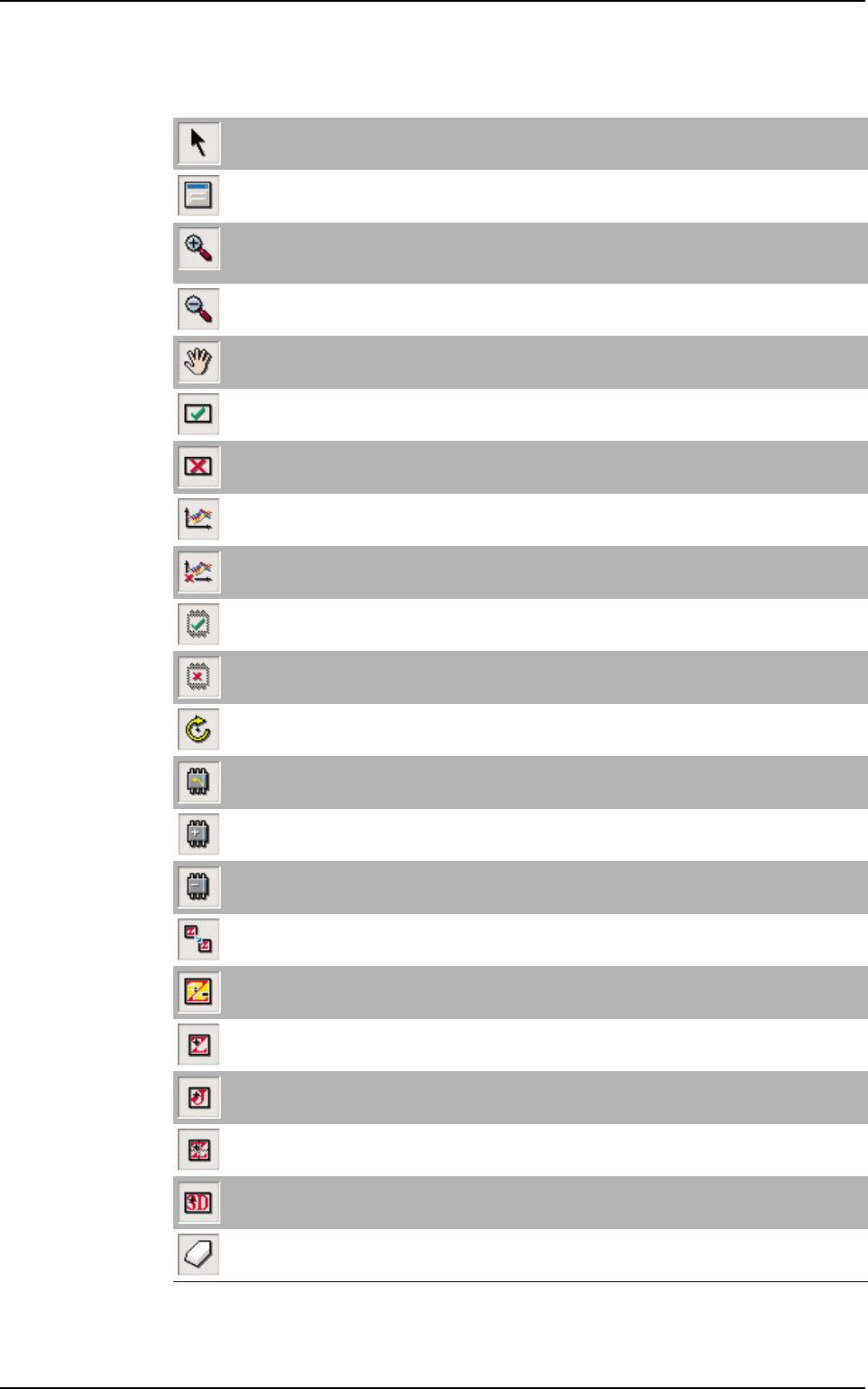
Selection
Select the different elements (component, paste pad, text, fiducial, skip, data matrix, bar code).
Edit
Open the edition window of the selected element.
Zoom +
Use Zoom + to enlarge the CAD view scale or click + on the numeric pad or use the mouse scroll.
It is also possible to draw a rectangle to define an area to zoom in.
Zoom - *
Use Zoom - to reduce the CAD view scale or click - on the numeric pad.
Move
Move the CAD view in the .tst file window. Press the space bar to change any icon to this one.
Test
Put the selected element in test.
No test *
Remove the selected element from test.
Set statistical flag
Put the selected element in statistical monitoring.
Clear statistical flag *
Remove the selected element from statistical monitoring.
Set missing flag *
Put the selected element in Test absent.
Clear missing flag *
Remove the selected element in Test absent.
Rotate component
Rotate the selected component through 90°.
Rotate polarity
Rotate the polarity of the selected component through 90°.
Add polarity*
Add polarity on the selected component.
Remove polarity *
Remove polarity on the selected component.
Move zone
Move the selected zone.
Show components in zone*
Show components and paste pads of the selected zone.
Add zone
Add zone at the pointed location of the CAD view.
Add joker zone *
Add joker zone centered around the pointed component of the CAD view.
Add centered zone *
Add centered zone and attach it to the pointed element.
Add 3D scan zone (only for Vi-3KD
3
100 % solder paste inspection) *
Add 3D scan zone.
Erase
Erase selected element (component, paste pad, zone, text, ID code ...).
Vision 2007 overview
Getting started
1 - 16 Vision2007 4.10 User Manual Rev 01
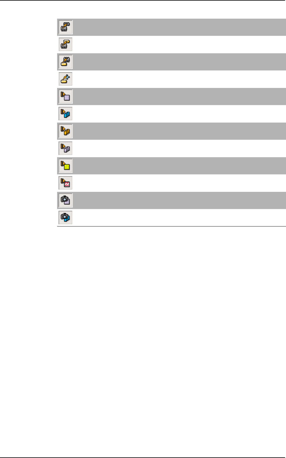
Convert component to connector
Convert selected component to connector.
Convert component to paste *
Convert selected component to paste pad.
Convert paste to component *
Convert selected paste pad to component.
Convert paste to Ref 3D (only for Vi-3KD
3
100 % solder paste inspection) *
Convert selected paste pad to 3D reference.
Run component
Test selected component.
Run by jedec
Test by jedec.
Run by PN *
Test by part number.
Run by reference designator *
Test by reference designator.
Run board
Test the board.
Run zone
Test the selected zone.
Reference designator picture
Record a picture of the selected reference designator.
Picture by jedec
Record pictures of all components of the same jedec name.
Vision 2007 overview
Vision 2007 4.10 User Manual Rev 01 2 - 1
Chapter 2
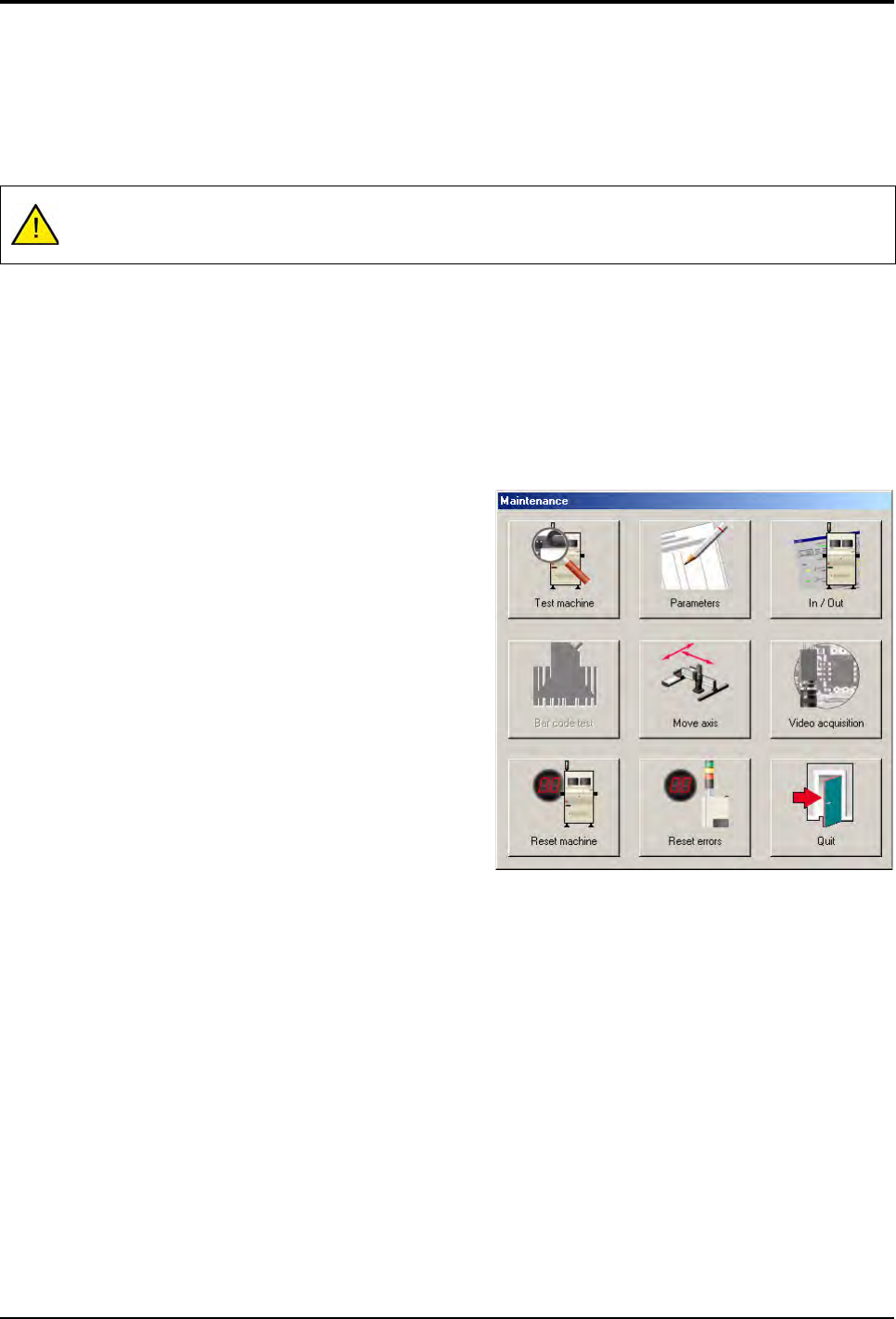
Maintenance mode
The Maintenance mode is used to access the various machine parameters, checks and configurations.
At the end of this chapter, you will be able to:
Calibrate and check the machine.
Access the various machine parameters.
Control the various machine parts separately.
Control axes movement manually, etc.
Click Maintenance button to access the functions of the
Maintenance mode from the Vision System window.
The Maintenance mode functions window appears.
Do not change adjustments if you are not authorized to do so. This mode may be protected by a pass-
word (see chapter 1).