VI User Manual.pdf - 第360页
Reparation 14 - 8 Vi sion 2007 4.10 User Manual Rev 01 14.3 Reparation use 14.3.1 Faults reporting After a board inspecti on or a board request on off-line m ode, the faults are disp layed in the faults reporting window.…
Reparation
Vision 2007 4.10 User Manual Rev 01 14 - 7
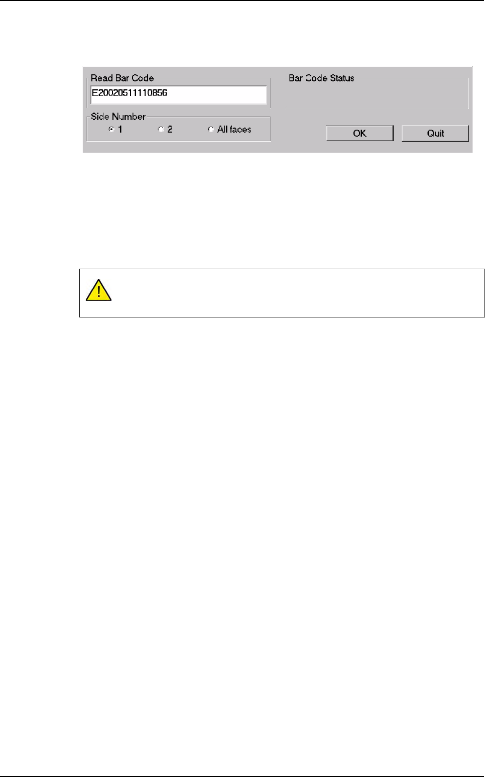
The operator requests board information by means of a scanner to read barcode information
or by using the keyboard.
14.2.4 Launching off-line FIFO (First In First Out)
The FIFO repair station is an off-line mode of the repair station. This mode works without bar-
code and the first board in error, stored in the database,will be the first repaired. When the
first board will be repaired, automatically, the software will display the 2nd board anomalies.
The Off-line FIFO mode setting up is the same as off-line mode. Select a product to repair
and the defects of the 1st board to repair are displayed.
It is forbidden to use the status: Invalid, Not repaired, Washed and Ejected.
Use only Good and Repaired status, otherwise you will lock up.
Reparation launching
Reparation
14 - 8 Vision 2007 4.10 User Manual Rev 01
14.3 Reparation use
14.3.1 Faults reporting
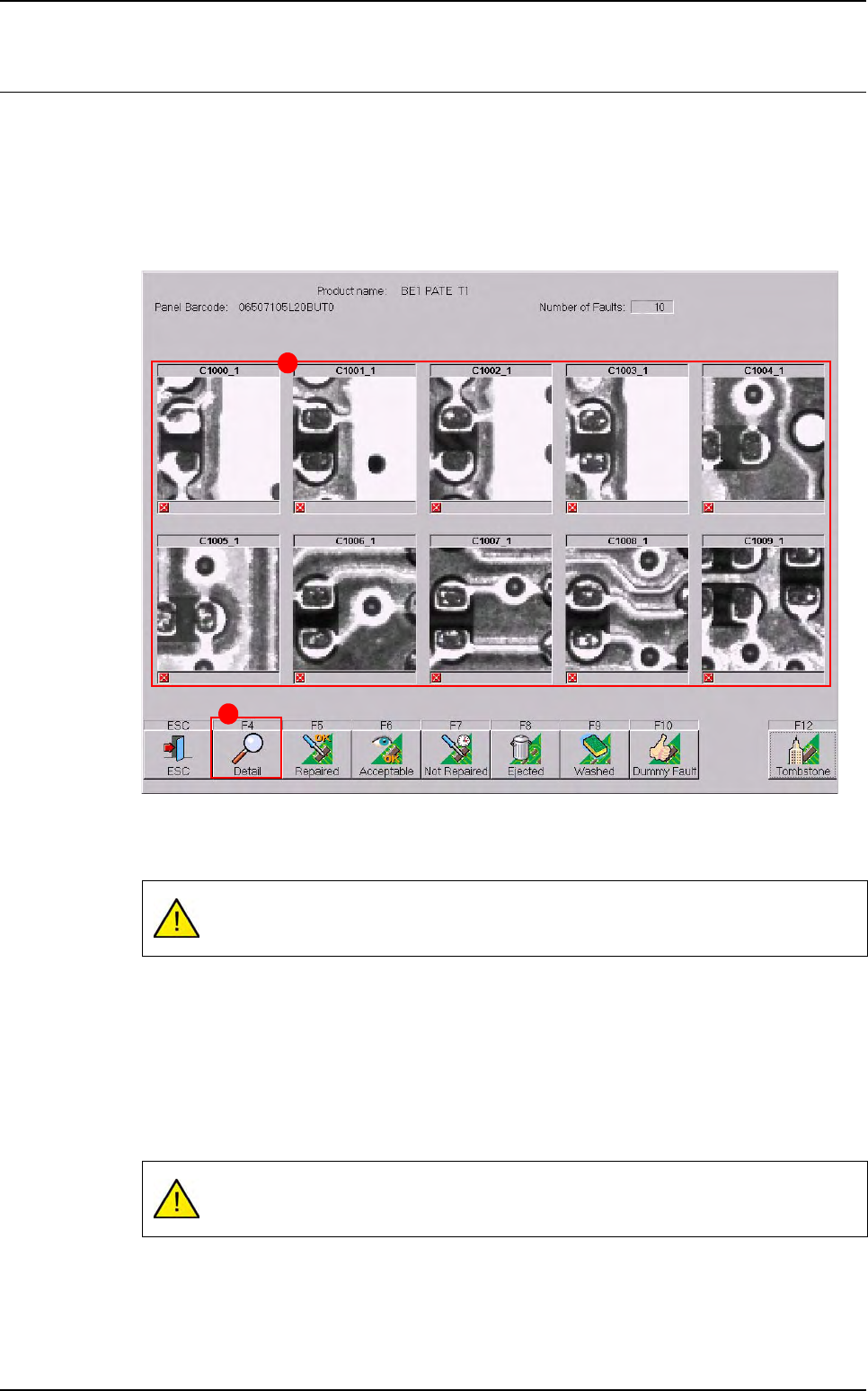
After a board inspection or a board request on off-line mode, the faults are displayed in the
faults reporting window. The button list of this window can be totally configured (see previous
pages).
The actual pictures (A) of the faults on the board and its Reference Designator are captured
by the AOI system.
Click on Detail (B) button to see more details of specific faults reported (see § 14.3.2 Rep-
aration detail).
All actions and decisions taken by the operator on the faults reported are stored in the su-
pervisor database, along with the board identification.
The number of images sent to the repair station is configurable in Vision 2007 software
(Maintenance menu / parameters / system). The button list of this window can be totally con-
figured (see § 14.2.1.2 Main and detail buttons windows).
Only a maximum of 10 faults appear on this screen (even if the camera takes more
pictures).
There is no picture saved for multi zones components errors so you can have a
blank picture.
B
A
Reparation
Vision 2007 4.10 User Manual Rev 01 14 - 9
14.3.2 Reparation detail
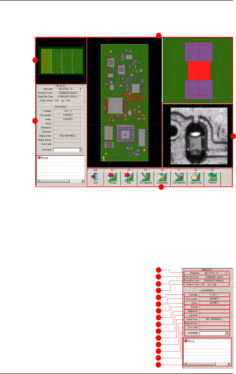
The screen below identifies all the information about the panel. It is divided in 5 main parts:
A Information about the panel and the defect.
B Graphic representation of the panel.
C Graphic representation of the board and the location of the defect. The board on which the
fault was detected is stripped. To access to the defects of any board click on them.
D A picture of the defect taken by the camera.
E The button list for the operator acknowledgement. The F3 and F4 button allows to pass to
the previous or next defect without treating the current one.
14.3.2.1 Panel information
A Test file name.
B Panel bar code of the current defect.
C Board bar code of the current defect.
D Remaining defects to repair.
E Reference designator of the current defect.
F Part number of the current defect.
G Customer name of the current defect.
H Feeder information.
I Reference of the component (coming from
the .Ref file).
J Comment on this component (coming from
the .Ref file).
A
B
C
D
E
F
G
H
I
J
K
L
M
N
O
Reparation use
B
A
E
C
D