VI User Manual.pdf - 第367页
Reparation Vision 2007 4.10 User Manua l Rev 01 14 - 15 Use the scroll bar to see the fid ucial you want to pick on the real picture. In the Fiducial selection w indow, ind icate the board num ber and the order of the se…
Reparation
14 - 14 Vision 2007 4.10 User Manual Rev 01
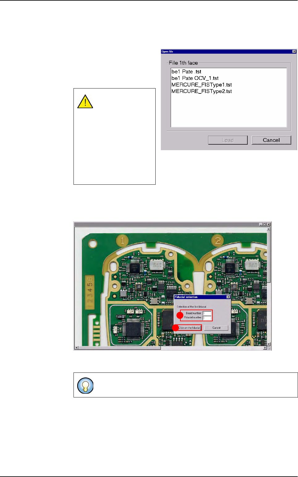
14.3.5.3 Real image
If you want to display the real picture of the board, you need to indicate the fiducials
positions in order to target the components.
Select the Real image menu,
the opposite window appears,
when you click on the wanted
.tst file, that display the real im-
age of this .tst file.
Select the 2 fiducials that are the furthest apart diagonally (must be fiducials that
are used in the .tst file). This will allow the software to find the components position
of the real picture.
Indicate the Board number and the Fiducial number (A) according to the .tst file
information and press Click on the fiducial (B) button.
The real image must
have the same name
as the .tst file, with
the extension .bmp.
If the .bmp file can
not be found in the in-
dicated folder, you
will have a message
(the path folder can
be changed in the .ini
file).
If Board number: 0 = panel.
B
A
Reparation use
Reparation
Vision 2007 4.10 User Manual Rev 01 14 - 15
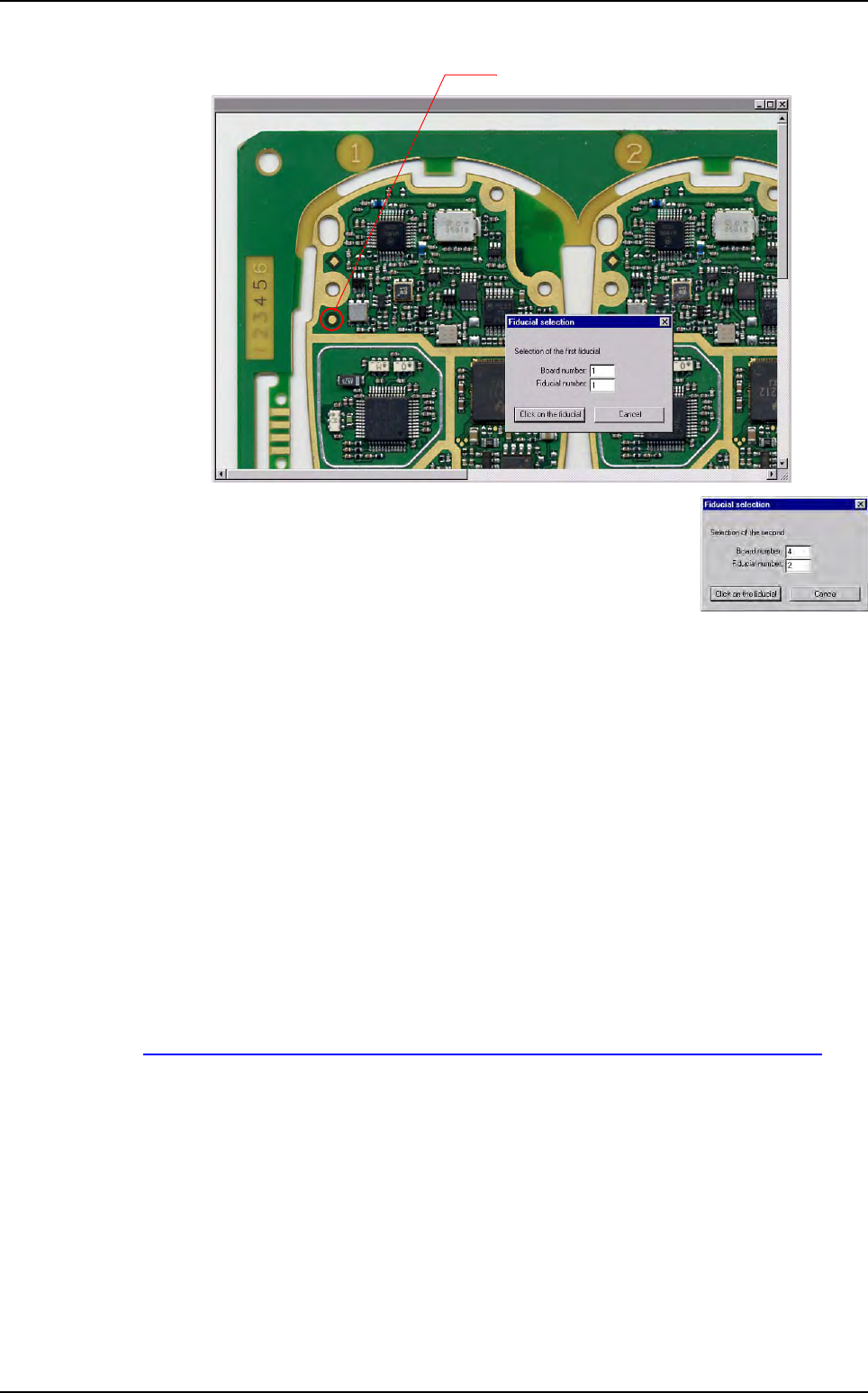
Use the scroll bar to see the fiducial you want to pick on the real picture.
In the Fiducial selection window, indicate the board number
and the order of the second fiducial, according to the .tst file
information and press Click on the fiducial button.
14.3.5.4 Password
You can use a password to limit access to the configuration menus. Every time you
want to access to the menu bar to configure the repair station (press Alt+F4), you
will be asked the password.
Enter the password and confirm it.
14.3.6 Bar code printing
This feature gives the opportunity to the operator to print a label (1D bar code) with the iden-
tifier of the inspection, in order to be able to repair offline afterwards.
The identifier may be a bar code or the date and time stamp of this inspection.
The supported printer is the Zebra bar code printer TLP 3842. It should be connected to the
parallel port of the PC.
The EPL table for Zebra printer is available on:
http://www.megacz.com/software/eltron/manuals/EPL2ProgrammersManual.pdf
This feature can be configured in ConfigReparation.ini file, in the [Barcode printer] sec-
tion.
Reparation use
Reparation
14 - 16 Vision 2007 4.10 User Manual Rev 01
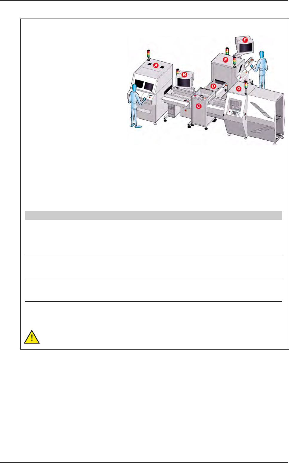
Repair status signal option
The repair status signal enables to
guide not repaired PCB after the oper-
ator diagnostic on the repair station.
This option is used when a diagnostic
station is placed after the AOI system
and when boards which need to be re-
paired later on must be oriented.
The diagnostic station runs with the
repair software connected to the data-
base.
In the repair software, the operator
gives a status for each defect.
If the board can not be repaired at this
stage and needs to be oriented, the
NO GOOD signal is sent to the IO
card after the operator release the
PCB.
PCB with the Not repaired status in
the database will be oriented.
To activate this option set the following parameters in the C:\VIT\ConfigReparation.ini file:
This option requires to have an I/O card in the diagnostic PC. Contact support to check your
equipment compatibility.
A AOI system
B Diagnostic station with Reparation software installed
C T conveyor
D Conveyor
E Buffer conveyor
F Repair station
G Downstream equipment
[Unloading board : Signal Cfg]
Send unloading signal state [0:1]=1 Unloading and state (optional) of the board
1: after repair diagnostic, the No good signal is sent on the B1 relay
of the I/O card i the PCB needs to be oriented.
0: will not send the No good signal after repair diagnostic even if the
PCB is still not repaired.
Start IO board driver [0:1]=1 Board driver activation
1: start the IO card driver
0: do not start the IO card driver
Reset state signal after unloading [0:1]=1 Signal reset
1: the No good signal come down after the specified signal time.
0: the No good signal stays ON until the next PCB.
Signal time (ms)=500 Signals activation time
Time to let the "acknowledge" and "No good" signal ON on the IO
card driver
Reparation use