VI User Manual.pdf - 第37页
Vision 2007 4.10 User Manua l Rev 01 2 - 1 Chapter 2 Maintenance mode The Mainten ance mode is used to access the various machine paramete rs, checks and configurations. At the end of this chapter, you will be able to: …
Getting started
1 - 16 Vision2007 4.10 User Manual Rev 01
Convert component to connector
Convert selected component to connector.
Convert component to paste *
Convert selected component to paste pad.
Convert paste to component *
Convert selected paste pad to component.
Convert paste to Ref 3D (only for Vi-3KD
3
100 % solder paste inspection) *
Convert selected paste pad to 3D reference.
Run component
Test selected component.
Run by jedec
Test by jedec.
Run by PN *
Test by part number.
Run by reference designator *
Test by reference designator.
Run board
Test the board.
Run zone
Test the selected zone.
Reference designator picture
Record a picture of the selected reference designator.
Picture by jedec
Record pictures of all components of the same jedec name.
Vision 2007 overview
Vision 2007 4.10 User Manual Rev 01 2 - 1
Chapter 2
Maintenance mode
The Maintenance mode is used to access the various machine parameters, checks and configurations.
At the end of this chapter, you will be able to:
Calibrate and check the machine.
Access the various machine parameters.
Control the various machine parts separately.
Control axes movement manually, etc.
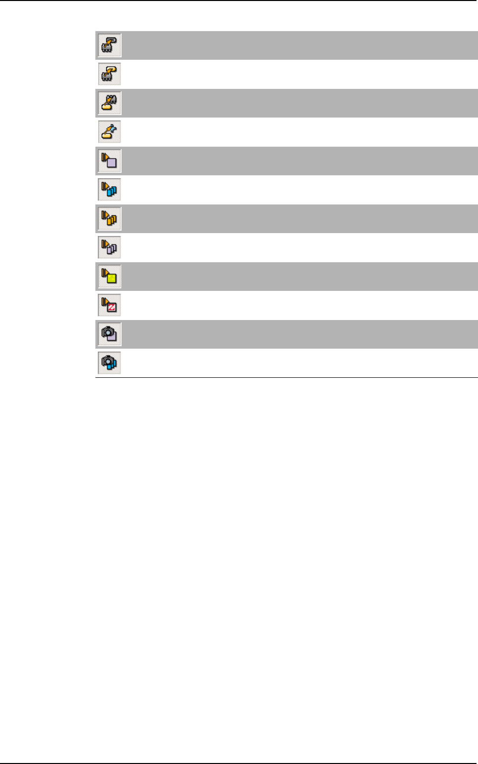
Click Maintenance button to access the functions of the
Maintenance mode from the Vision System window.
The Maintenance mode functions window appears.
Do not change adjustments if you are not authorized to do so. This mode may be protected by a pass-
word (see chapter 1).
Maintenance mode
2 - 2 Vision 2007 4.10 User Manual Rev 01
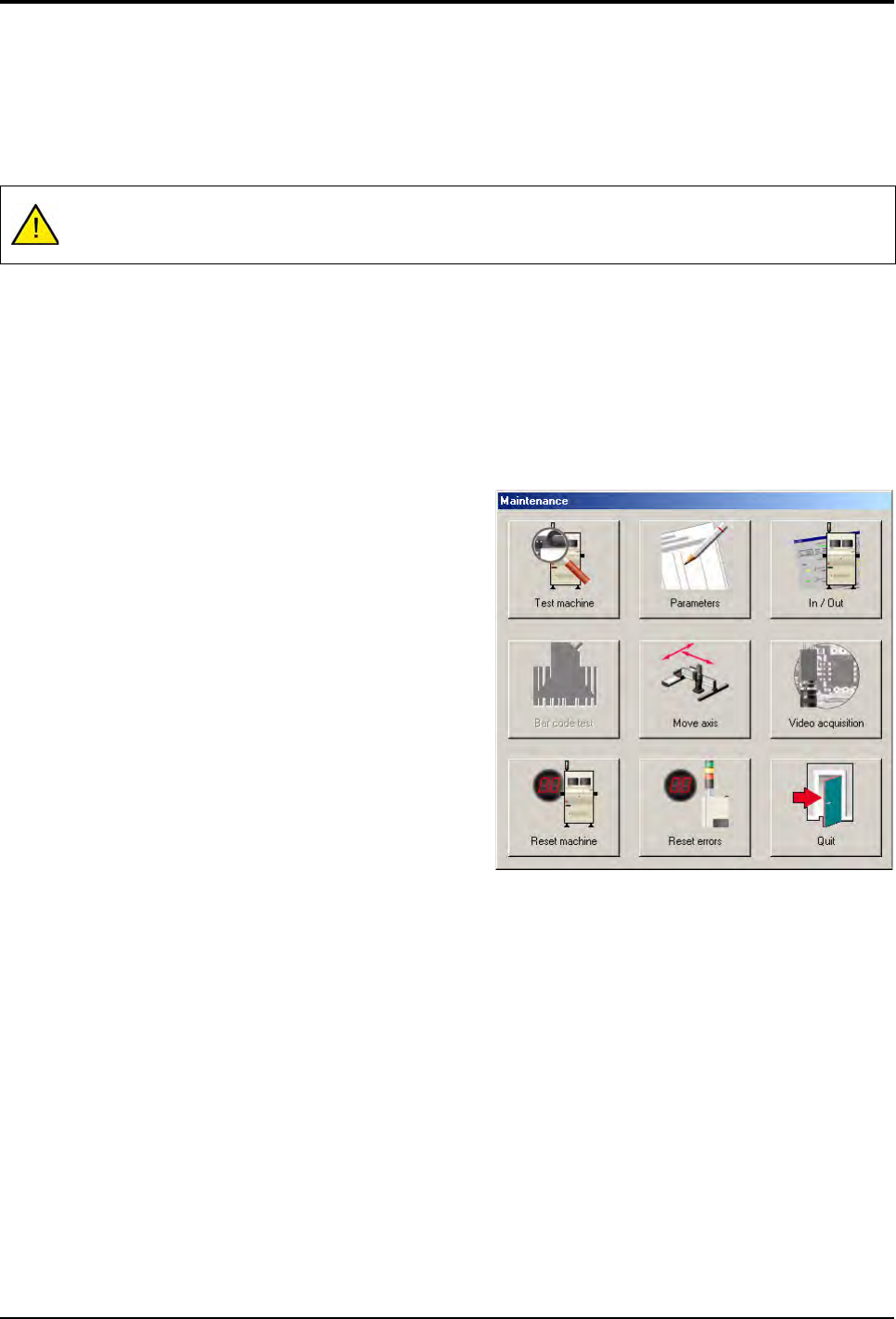
2.1 Test machine
When you click on Test machine button, the opposite screen appears with the calibration functions of
the AOI system.
2.1.1 Gray levels
Calibration of the gray levels ensures the same degree of light intensity and performance of the
lighting head is obtained for every machine by selection of a reference gray level (120).
Consequently, any lighting combination on any machine placed on any production lines through-
out the world will provide the same lighting ranges.
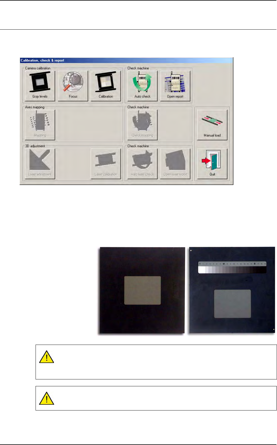
The gray levels is cali-
brated using the gray
tool supplied with the
machine.
Two tool versions are
available.
The standard gray paper used to create the tool have a life time of 1 year, if it is kept
away from light and humidity.
Contact support to change the standard gray paper each year.
On completion of gray level calibration, the focus may have changed as a result of gray
level adjustment.