VI User Manual.pdf - 第44页
Maintenance mode 2 - 8 Vision 2007 4.10 User Manual Re v 01 Axis angle ( A ): check the angle and the linear ity of the XY axes. Axis step ( B ): check the pitch of the XY axes. Balance of axis ( C ): check that the ca m…
Maintenance mode
Vision 2007 4.10 User Manual Rev 01 2 - 7
1.
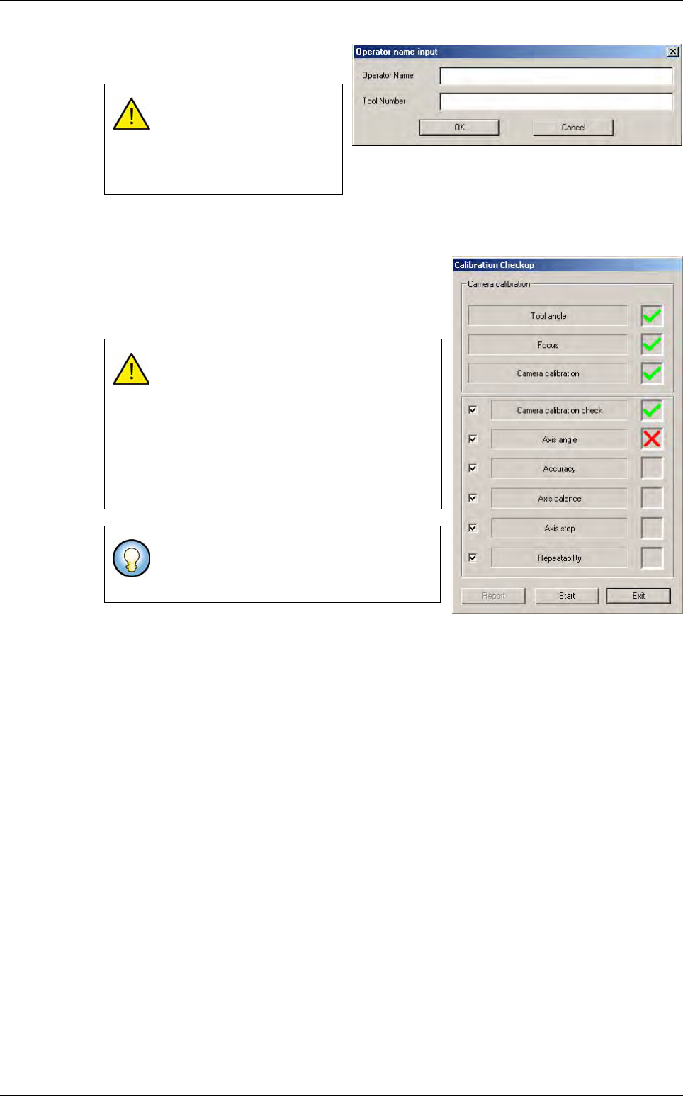
Click on
Auto check
to bring up the
data input window.
2.
After the
CONVEYOR INITIALIZATION
message, you can install the calibration tool in the ma-
chine.
3.
Once the calibration tool has been installed in the ma-
chine, the opposite screen is brought up.
4. Press Start to measure the tool angle and run the auto
check.
Each test checks a specific part of the machine. During the auto check, a green tick appears if
the relevant test is correct. Otherwise, a red cross is displayed if the test results are incorrect.
The Report button open the report of the check that has just been carried out (see next page).
To validate OK, the text fields
must be filled in (at least 2
characters). All glass tools
have a specific serial num-
ber.
The Auto check can only be run when the an-
gle between the calibration tool and the axis
is zero (0 +/- 0.07 degrees).
Otherwise, the value of the auto specification
angle appears and the clamps release the
board. You must then adjust it manually and
restart measurement until the angle is OK
and the test can begin.
The tool must be adjusted manually. Turn the
calibration tool in a clockwise direction if the
tool angle is negative and vice versa.
Test machine
Maintenance mode
2 - 8 Vision 2007 4.10 User Manual Rev 01
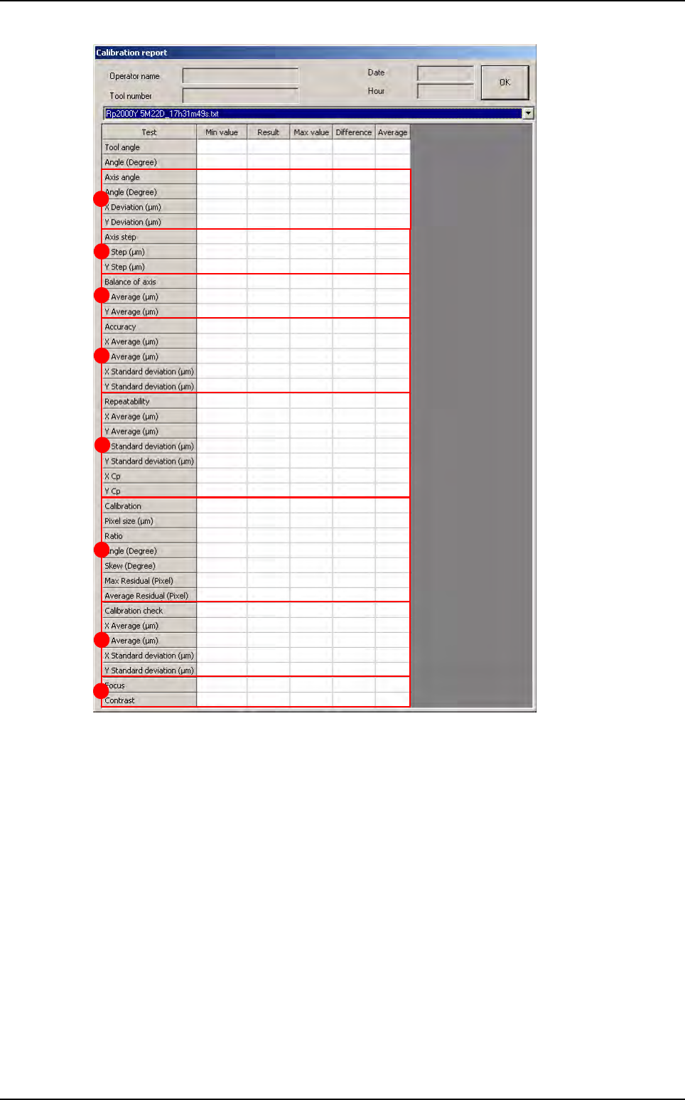
Axis angle (A): check the angle and the linearity of the XY axes.
Axis step (B): check the pitch of the XY axes.
Balance of axis
(
C
): check that the camera movement direction does not affect the measurement.
Accuracy (D): check measurement accuracy: points on the calibration tool are measured and
are used to obtain the average and the standard deviation between the measured position and
the theoretical position.
Repeatability (E): check average, standard deviation and capability (0.2/6 standard deviation)
of the machine.
Calibration (F):
Pixel size.
Ratio between pixel size in X and Y.
Angle between the camera and its holder.
Skew: parallelism between the camera plane and the calibration tool.
Residual max.: maximum distortion on the calibration matrix.
Residual average: average distortion on the calibration matrix.
A
B
C
D
E
F
G
H
Test machine
Maintenance mode
Vision 2007 4.10 User Manual Rev 01 2 - 9
Calibration check (G).
Focus (H): check camera focus.
2.1.5 Open report
This function allows you to read the previous machine check reports found in C:/VIT/report.
2.1.6 Manual load
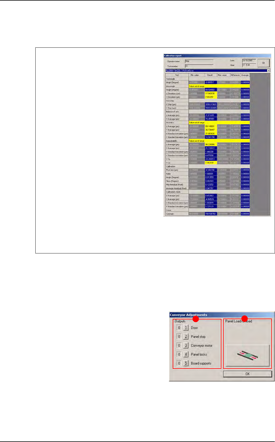
Outputs (A): each of the 5 buttons enables you to
activate one of the items listed.
Panel Load/uUnload (B): click on the Load/Un-
load button to automatically load and unload the
board.
Test failure is clearly marked in the report (yel-
low text fields for off-limit values and red text
fields for failed measurements, that are normally
due to unsuitable lighting or a dirty glass-plate).
The reasons for failed axes balance are:
Holding the camera in the wrong position.
Vibrations at lens level.
Incorrect fastening of the lens protective cover.
The reasons for failed accuracy are:
Wrong axis angle.
Wrong axis step.
The reasons for failed repeatability are:
Vibrations at camera level.
A dirty calibration tool.
If the calibration check fails, it means that calibration parameters in the memory do not match
the physical conditions of the camera. In this case, recalibrate the pixel size with the Calibra-
tion menu.
A
B
Test machine