VI User Manual.pdf - 第53页
Maintenance mode Vision 2007 4.10 User Manua l Rev 01 2 - 17 2.3 In / Out This window lets you check the various parts of the AOI system separately. Output commands ( A ): override o r activate comma nds. Lighting ( B ):…
Maintenance mode
2 - 16 Vision 2007 4.10 User Manual Rev 01
In this file the user could find the following information:
Generals information concerning the inspection:
AOI computer name.
Lane number (it is useful for a dual lane AOI). A checkbox allows to use or not.
Board: product name (= inspection program name).
Date-time of the inspection.
IDs: the panel (or sub-panel) identification.
Information concerning component inspection:
Blocks:Ref: component\pad identification and sub-panel number.
Mc-Feeder (empty for paste pads).
Package corresponds to the Jedecs of the component.
ImgQuality represents presence score for components and calculated surface for
solder paste (measured area / expected area * 100; %).
Angle of the component on the panel (found in the CAD data; clockwise; degree).
dX: deviation of the component/paste pad on the X axis (µm).
dY: deviation of the component/paste pad on the Y axis (µm).
dTheta: rotation of the component (degree). Empty for paste pads.
ErrCode: 0 if the component/paste pad is faulty, 1 if it is good.
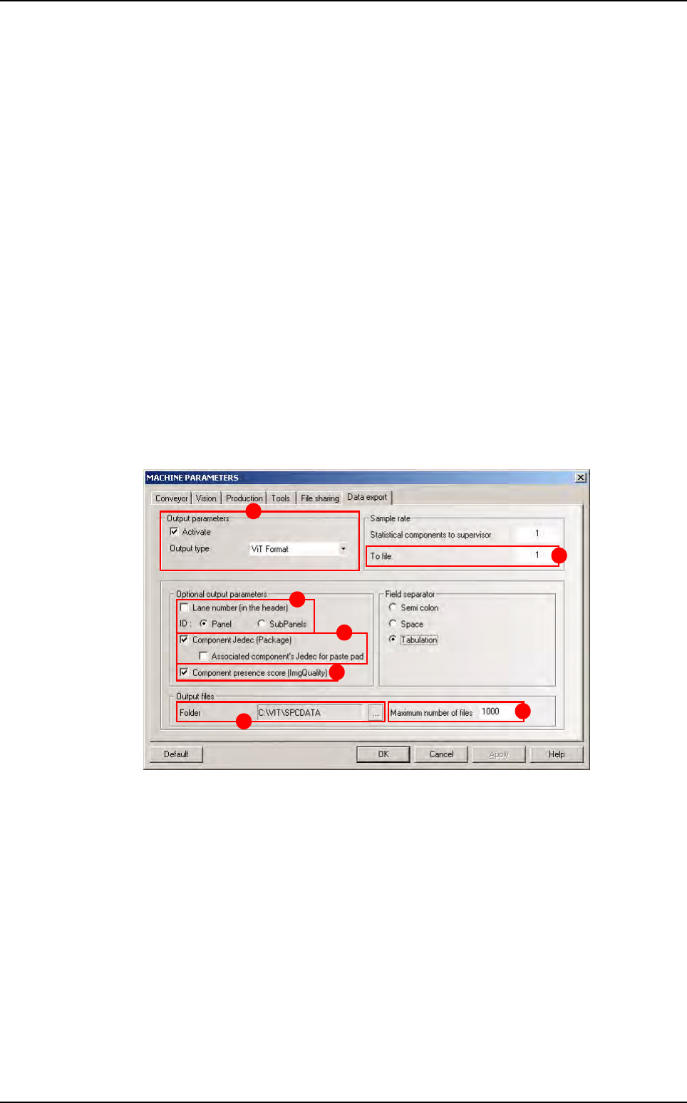
Activation and settings
In Output parameters section (A), tick Activate and choose the ViT Format. the
screen bellow appears.
Tick Lane number (in the header) (B) to add the lane number in the header. By default,
it is unchecked in order to ensure the compatibility with the previous version.
2 radio buttons allow choosing between put the Panel ID in the header or the list of each
Subpanel IDs.
Tick Component Jedec (Package) (C) to put the package column or not. An additional
checkbox allows, for a paste pad, to put the jedec of its associated component, or let this
field empty.
Tick Component presence score (ImgQuality) (D) to put the ImgQuality column or
not.
Select the path of the folder where the files (E) are generated.
The Maximum number of files (F) field allows specifying the maximum number of files
in the output folder. 0 = no limit.
The To file field (G) allows specifying a sampling rate (a file is generated for one panel
out of n).
A
B
C
D
E
F
G
Parameters
Maintenance mode
Vision 2007 4.10 User Manual Rev 01 2 - 17
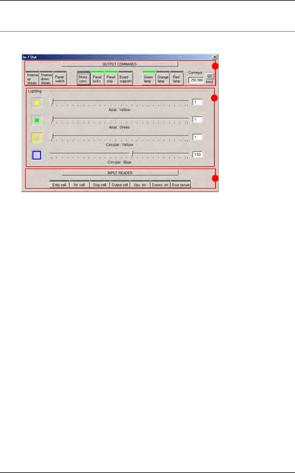
2.3 In / Out
This window lets you check the various parts of the AOI system separately.
Output commands (A): override or activate commands.
Lighting (B): individual adjustment of lighting levels.
Input reader (C): reading or checking input signals.
C
A
B
Maintenance mode
2 - 18 Vision 2007 4.10 User Manual Rev 01
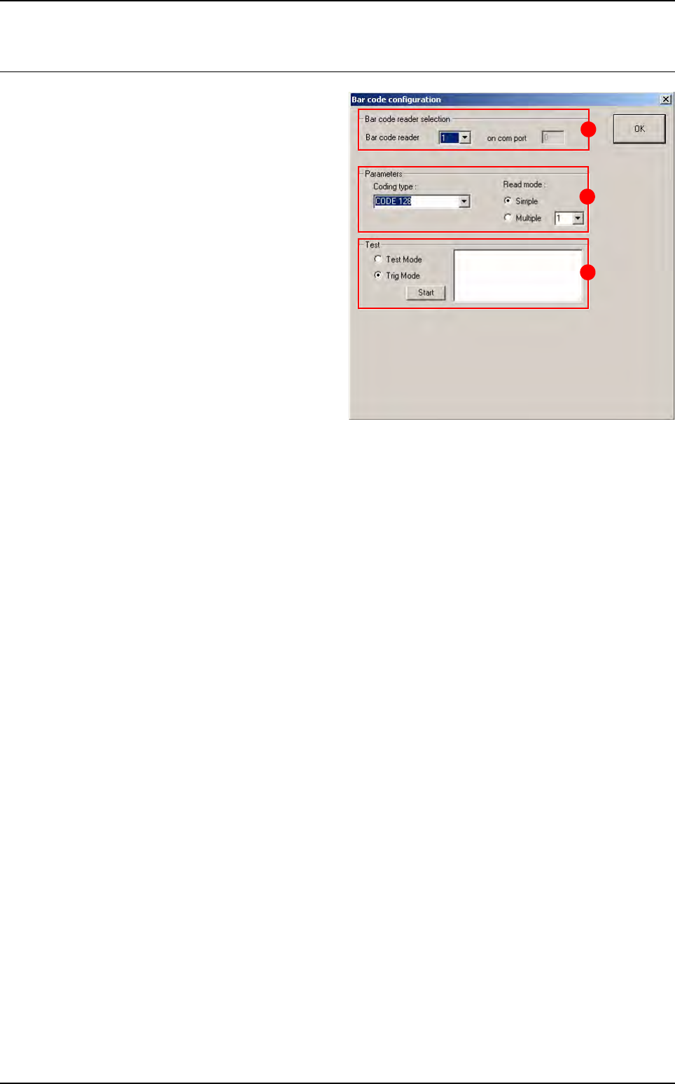
2.4 Bar code test
To check whether your bar code reader is oper-
ating properly and whether your bar code type
has been properly specified.
In Bar code reader selection (A) section, if the
AOI system is equipped with several readers,
select either one to run the test.
In Parameters (B) section: specify the type of
the bar code and the type of read mode.
In Test (C) section:
Tick Test Mode to use the bar code in perma-
nent read mode and view the percentage of
correct reading.
Tick Trig Mode to simulate board entry and
read the bar code once only.
The read code is displayed in the field.
B
A
C