VI User Manual.pdf - 第54页
Maintenance mode 2 - 18 Vision 2007 4.10 User Manual Re v 01 2.4 Bar code test To check whether you r bar code reader is oper- ating properly a nd whether your bar code type has been properly specified. In Bar code reade…
Maintenance mode
Vision 2007 4.10 User Manual Rev 01 2 - 17
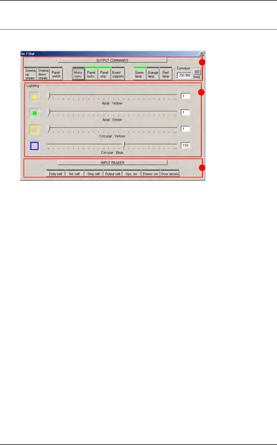
2.3 In / Out
This window lets you check the various parts of the AOI system separately.
Output commands (A): override or activate commands.
Lighting (B): individual adjustment of lighting levels.
Input reader (C): reading or checking input signals.
C
A
B
Maintenance mode
2 - 18 Vision 2007 4.10 User Manual Rev 01
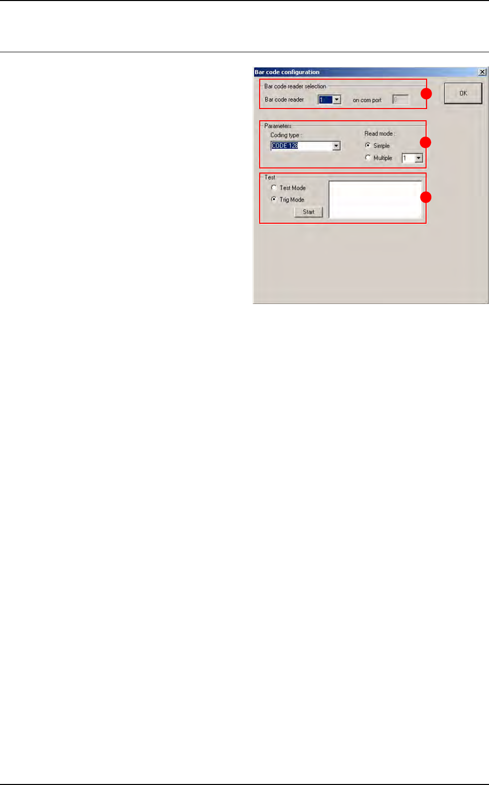
2.4 Bar code test
To check whether your bar code reader is oper-
ating properly and whether your bar code type
has been properly specified.
In Bar code reader selection (A) section, if the
AOI system is equipped with several readers,
select either one to run the test.
In Parameters (B) section: specify the type of
the bar code and the type of read mode.
In Test (C) section:
Tick Test Mode to use the bar code in perma-
nent read mode and view the percentage of
correct reading.
Tick Trig Mode to simulate board entry and
read the bar code once only.
The read code is displayed in the field.
B
A
C
Maintenance mode
Vision 2007 4.10 User Manual Rev 01 2 - 19
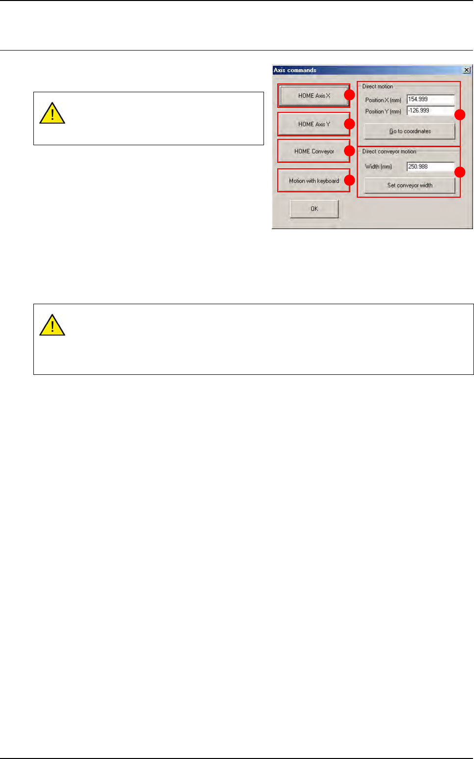
2.5 Move axis
The axis command gives you access to various
functions on the axis motors.
Press HOME Axis X (A) button to start initialization of
the X axis.
Press HOME Axis Y (B) button to start initialization of
the Y axis.
Press HOME Conveyor (C) button to start initializa-
tion of the conveyor.
Press Motion with keyboard (D) button to control the movement of the XY axes manually using the
arrow keys on the keyboard. Use the page up / down keys to vary the movement step of the axes.
In Direct motion (E) section, enter the XY coordinates of the position to which you wish the camera to
move. Press Go to the coordinates button once you have entered the values in the boxes above.
In Direct conveyor motion (F) section, press Set conveyor width button to automatically adjust con-
veyor width once you have entered the relevant value.
All the boards in the conveyor will be auto-
matically unloaded when the conveyor is ad-
justed.
These are the real coordinates of the axis read by the machine and not the coordinates mea-
sured from the origin (0,0). These coordinates will be used as XY conveyor references in MA-
CHINE PARAMETERS.
Incorrect coordinates can damage the axis.
A
B
C
D
E
F