VI User Manual.pdf - 第56页
Maintenance mode 2 - 20 Vision 2007 4.10 User Manual Re v 01 2.6 Video acquisition This mode gives you a direct ima ge of the camera. When you start that mode, the oppo site box ap- pears, in wh ich you choose your type …
Maintenance mode
Vision 2007 4.10 User Manual Rev 01 2 - 19
2.5 Move axis
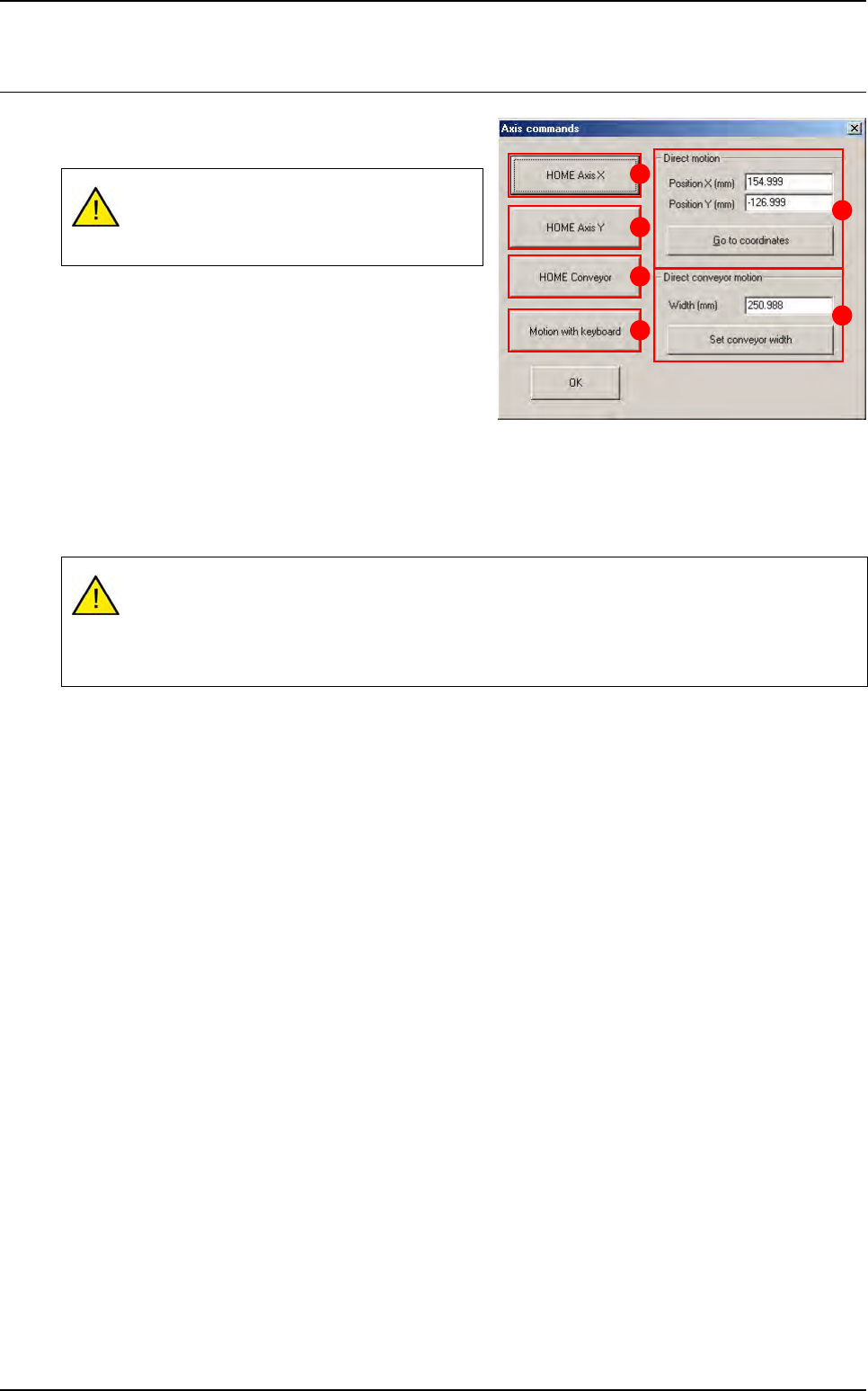
The axis command gives you access to various
functions on the axis motors.
Press HOME Axis X (A) button to start initialization of
the X axis.
Press HOME Axis Y (B) button to start initialization of
the Y axis.
Press HOME Conveyor (C) button to start initializa-
tion of the conveyor.
Press Motion with keyboard (D) button to control the movement of the XY axes manually using the
arrow keys on the keyboard. Use the page up / down keys to vary the movement step of the axes.
In Direct motion (E) section, enter the XY coordinates of the position to which you wish the camera to
move. Press Go to the coordinates button once you have entered the values in the boxes above.
In Direct conveyor motion (F) section, press Set conveyor width button to automatically adjust con-
veyor width once you have entered the relevant value.
All the boards in the conveyor will be auto-
matically unloaded when the conveyor is ad-
justed.
These are the real coordinates of the axis read by the machine and not the coordinates mea-
sured from the origin (0,0). These coordinates will be used as XY conveyor references in MA-
CHINE PARAMETERS.
Incorrect coordinates can damage the axis.
A
B
C
D
E
F
Maintenance mode
2 - 20 Vision 2007 4.10 User Manual Rev 01
2.6 Video acquisition
This mode gives you a direct image of the camera.
When you start that mode, the opposite box ap-
pears, in which you choose your type of camera.
The different check box allow you to flick through the
cameras:
If you check Inside camera, we display a live image
of the camera used for component inspection.
If you check Outside camera, we display a live im-
age of the camera used to read Data Matrix.
If you check 3D camera (only for Vi-3200 and Vi-5000), we display a live image of the camera used for
paste height inspection.
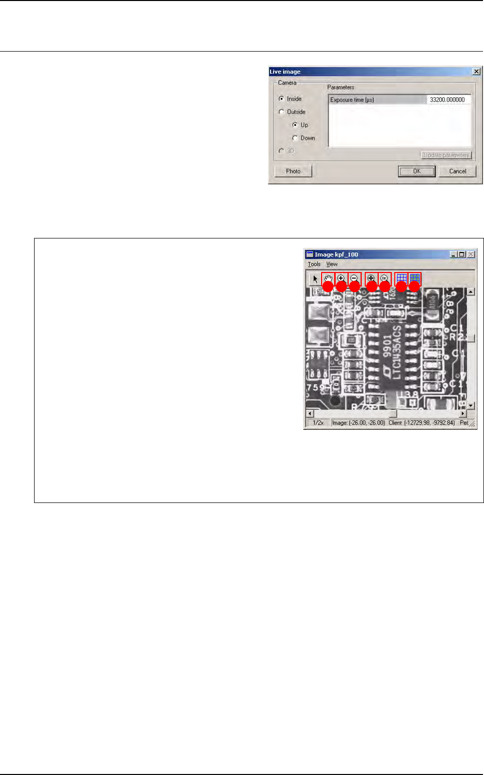
The Photo button allows you to save current live image in a .bmp format file in the C:\Temp folder.
You must activate the Image window to view the image
taken.
The Hand (A) tool enables the image to be moved around
the image display window.
With Zoom + (B) click on the image with the left mouse but-
ton to enlarge the image display scale and with the right
mouse button to reduce it.
With Zoom - (C) click on the image with the left mouse but-
ton to reduce the image display scale and with the right
mouse button to enlarge it.
This
Best fit
(
D
) tool enables the image display window to be
enlarged to a maximum by adapting it to the screen size.
The 1x (E) tool brings you back to the original size of the
image display window.
The Pixel mapping (F) function gives you on the screen, provided the enlargement is sufficient (ap-
prox. 3x), a grid representing the pixels.
The Sub pixel mapping (G) function gives you on the screen a grid representing the sub-pixels.
A B C D E F G

Maintenance mode
Vision 2007 4.10 User Manual Rev 01 2 - 21
2.7 Reset machine, reset error, quit
Reset machine will re-initial-
ize the AOI system and its
various parts such as the
axis controller and the bar
code reader. The message above appears during re-initialization.
If you have an error message accompanied by a light signal coming from the light tower (e.g. a
conveying error, etc.) press Reset errors.
Quit lets you leave the MAINTENANCE MODE and return to Vision 2007 main screen.