VI User Manual.pdf - 第58页
在线预览 VI User Manual.pdf PDF 文档。

Maintenance mode
Vision 2007 4.10 User Manual Rev 01 2 - 21
2.7 Reset machine, reset error, quit
Reset machine will re-initial-
ize the AOI system and its
various parts such as the
axis controller and the bar
code reader. The message above appears during re-initialization.
If you have an error message accompanied by a light signal coming from the light tower (e.g. a
conveying error, etc.) press Reset errors.
Quit lets you leave the MAINTENANCE MODE and return to Vision 2007 main screen.
Vision 2007 4.10 User Manual Rev 01 3 - 1
Chapter 3
.VIS file
3.1 .VIS file description
The .vis file is a text file used to create the inspection program.
CAD coordinates
⇒ .vis file ⇒ .tst file.
This chapter will guide you around the main functions of Vision 2007 to enable you to create a .vis file
containing all the data required to create a graphic representation of the board panel.
The .vis file can be created in 3 ways:
Manually, using any text editor software. You can also use MS Excel (processing by lines and col-
umns, important for importing CAD data), but you must save the file in text format.
Automatically, using converters installed beforehand according to the CAD format used: FABMas-
ter®, UNICAM®, CIRCUITCAM® and others.
Automatically, using ViTECHNOLOGY built in CAD converter: VIS file wizard (see § 3.2 .VIS file
builder, for description).
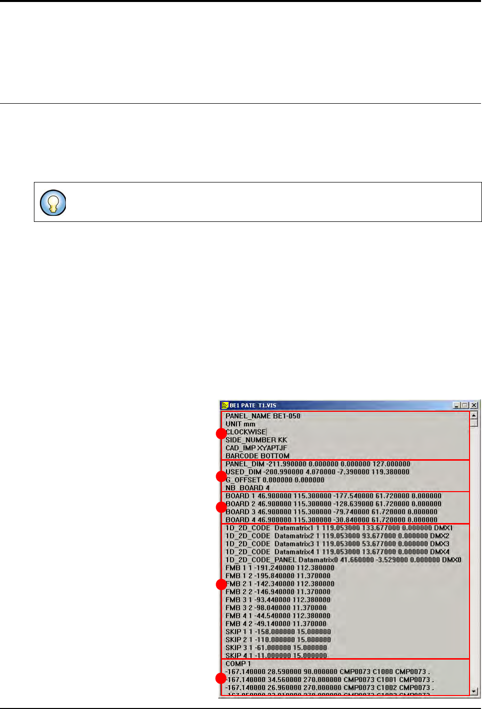
3.1.1 Structure of the .vis file
The .vis file contains all the CAD data and the information concerning panel arrangement.
The .vis file is divided into 5 dif-
ferent sections:
General description (A),
Panel information (B),
Board arrangement (C),
Data matrix, fiducial and skip (
D
),
CAD coordinates (E).
The graphic representation is a .tst file which has been generated from a .vis file.
A
B
C
D
E