VI User Manual.pdf - 第60页
.VIS file 3 - 2 Vision 2007 4.10 User Manual Re v 01 3.1.2 Description in the machine reference 3.1.2.1 File header-block G_OFFSET It is the offset between the machine refere nce and the CAD file reference. Example 3.1.2…
Vision 2007 4.10 User Manual Rev 01 3 - 1
Chapter 3
.VIS file
3.1 .VIS file description
The .vis file is a text file used to create the inspection program.
CAD coordinates
⇒ .vis file ⇒ .tst file.
This chapter will guide you around the main functions of Vision 2007 to enable you to create a .vis file
containing all the data required to create a graphic representation of the board panel.
The .vis file can be created in 3 ways:
Manually, using any text editor software. You can also use MS Excel (processing by lines and col-
umns, important for importing CAD data), but you must save the file in text format.
Automatically, using converters installed beforehand according to the CAD format used: FABMas-
ter®, UNICAM®, CIRCUITCAM® and others.
Automatically, using ViTECHNOLOGY built in CAD converter: VIS file wizard (see § 3.2 .VIS file
builder, for description).
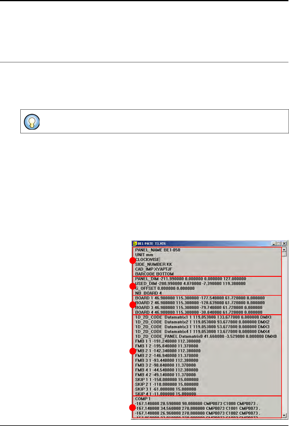
3.1.1 Structure of the .vis file
The .vis file contains all the CAD data and the information concerning panel arrangement.
The .vis file is divided into 5 dif-
ferent sections:
General description (A),
Panel information (B),
Board arrangement (C),
Data matrix, fiducial and skip (
D
),
CAD coordinates (E).
The graphic representation is a .tst file which has been generated from a .vis file.
A
B
C
D
E
.VIS file
3 - 2 Vision 2007 4.10 User Manual Rev 01
3.1.2 Description in the machine reference
3.1.2.1 File header-block
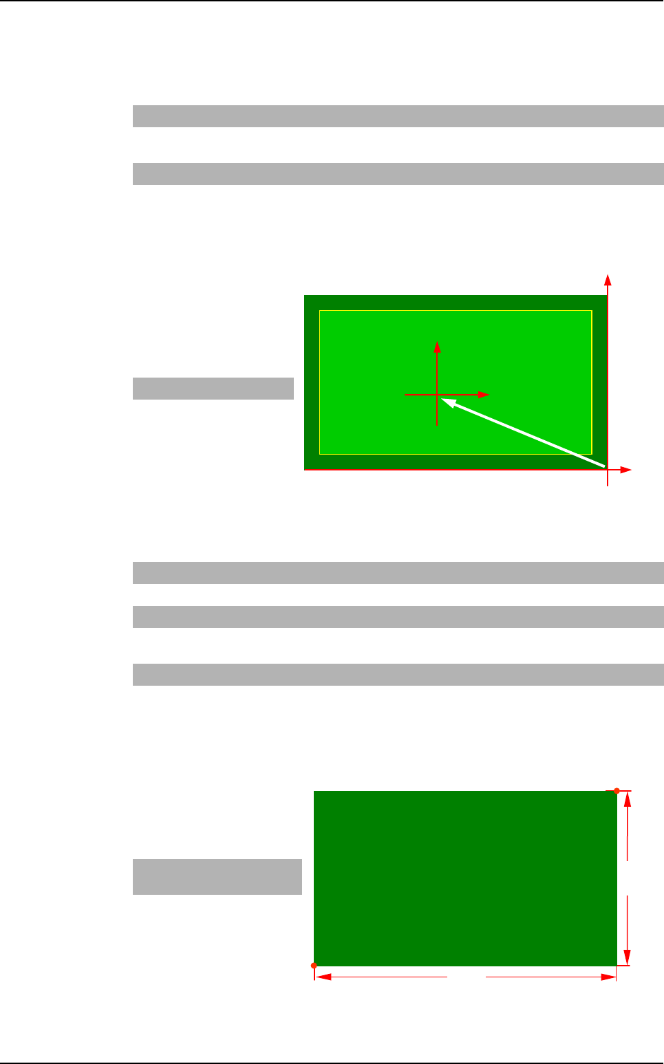
G_OFFSET
It is the offset between the
machine reference and the
CAD file reference.
Example
3.1.2.2 Panel information
PANEL_DIM
It is the dimension of the panel.
Example
PANEL_NAME Abc Name of board, panel or product.
CLEAR Leave this
space blank
Deletes the old .tst file. If the command is not available, the changes are
added in the existing .tst file (not used anymore).
UNIT mm or inches Measurement unit used.
G_OFFSET x0, y0 Offset between the CAD origin and the machine origin (bottom right-hand
corner of the board).
X dim Y dim
- 7 3
SIDE_NUMBER
xx Side name (2 characters max.).
BARCODE
TOP or BOTTOM
Location of the bar code (not used anymore).
PANEL_DIM X1, Y1, X2, Y2 Panel dimension: bottom left-hand corner and top right-hand corner.
USED_DIM X1, Y1, X2, Y2 Panel useful dimension: bottom left-hand corner and top right-hand cor-
ner.
NB_BOARD Enter a number Number of boards on the panel.
CLOCKWISE
or COUNTER_
CLOCKWISE
Leave this
space blank
Component rotation direction. By default: clockwise.
X Bot-
tom Left
Y Bot-
tom Left
X Top
Right
Y Top
Right
- 78 0 0 45
(X0, Y0)
Machine
reference
CAD
reference
(0, 0)
G_OFFSET
Y dim
X dim
(X0, Y0)
Top Right
Bottom Left
.VIS file description
.VIS file
Vision 2007 4.10 User Manual Rev 01 3 - 3
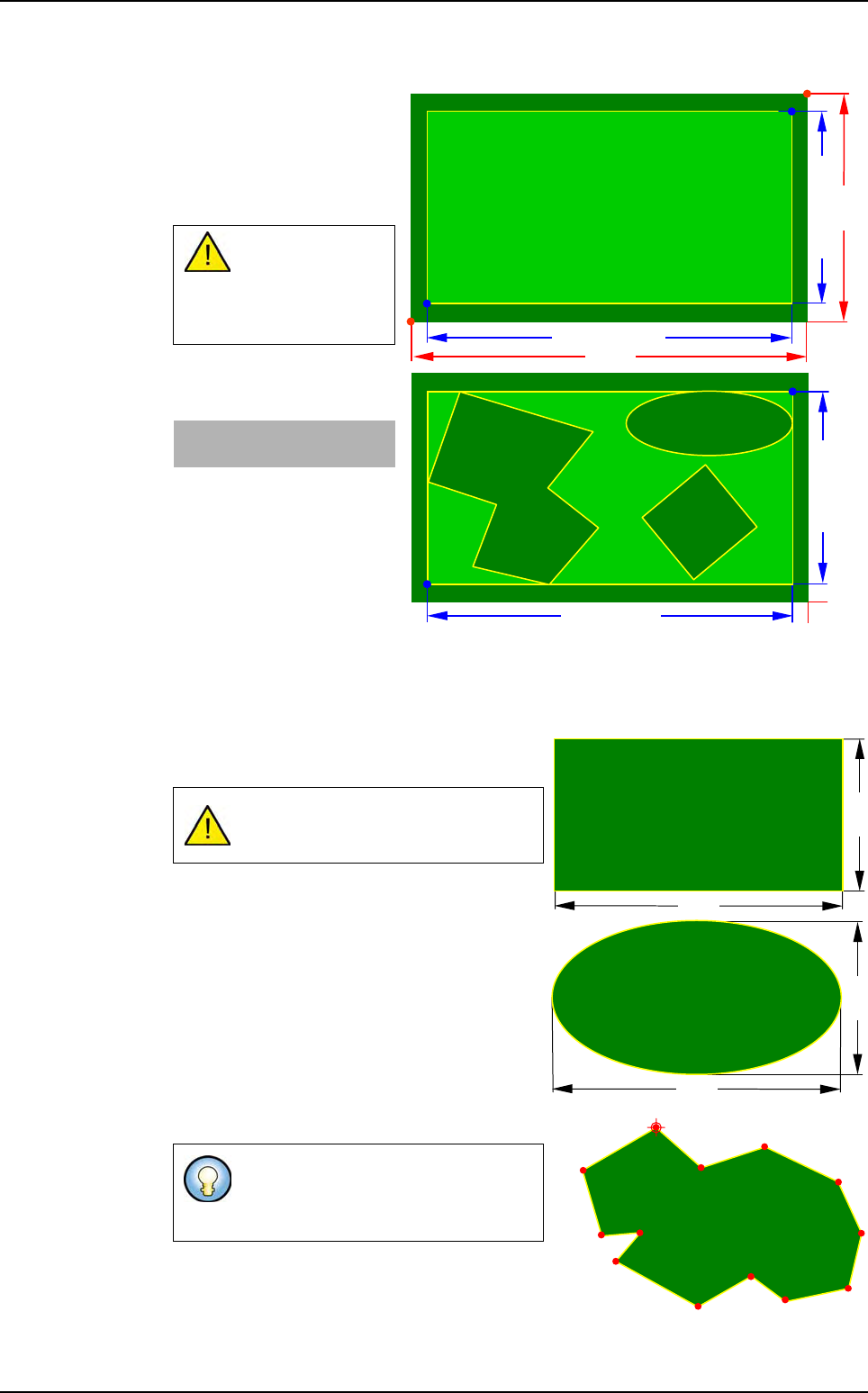
USED_DIM
It is the dimension of the
panel useful zone, whether
single or multiple board,
containing all the compo-
nents to be inspected.
Example
3.1.2.3 Description mode of the panel boards
3 board shapes are used: rectangle, ellipse and polygon:
Rectangle and ellipse shapes are defined by a
width and a height.
Polygon shape is defined by a series of points.
USED_DIM must
always be less
than or equal to
PANEL_DIM.
X Bot-
tom Left
Y Bot-
tom Left
X Top
Right
Y Top
Right
- 78 0 0 45
In Ellipse shape the angle can only be
at 0, 90, 180, 270°.
The origin point (the first point) is the
start of the board drawing and its
rotation axis.
Y dim
X dim
(X0, Y0)
Top Right
Bottom Left
USED_DIM Y
USED_DIM -X
(X0, Y0)
USED_DIM -X
USED_DIM Y
Height
Width
Width
Height
Origin point
.VIS file description