VI User Manual.pdf - 第61页
.VIS file Vision 2007 4.10 User Manua l Rev 01 3 - 3 USED_DIM It is the dimension of the panel useful zone, whether single or mu ltiple board , containing all the compo- nents to be inspected. Example 3.1.2.3 Description…
.VIS file
3 - 2 Vision 2007 4.10 User Manual Rev 01
3.1.2 Description in the machine reference
3.1.2.1 File header-block
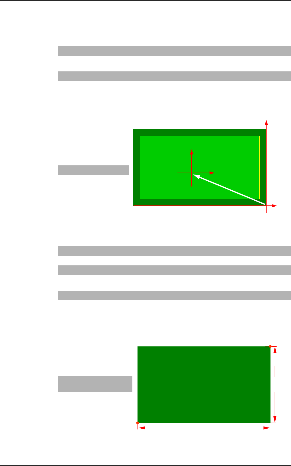
G_OFFSET
It is the offset between the
machine reference and the
CAD file reference.
Example
3.1.2.2 Panel information
PANEL_DIM
It is the dimension of the panel.
Example
PANEL_NAME Abc Name of board, panel or product.
CLEAR Leave this
space blank
Deletes the old .tst file. If the command is not available, the changes are
added in the existing .tst file (not used anymore).
UNIT mm or inches Measurement unit used.
G_OFFSET x0, y0 Offset between the CAD origin and the machine origin (bottom right-hand
corner of the board).
X dim Y dim
- 7 3
SIDE_NUMBER
xx Side name (2 characters max.).
BARCODE
TOP or BOTTOM
Location of the bar code (not used anymore).
PANEL_DIM X1, Y1, X2, Y2 Panel dimension: bottom left-hand corner and top right-hand corner.
USED_DIM X1, Y1, X2, Y2 Panel useful dimension: bottom left-hand corner and top right-hand cor-
ner.
NB_BOARD Enter a number Number of boards on the panel.
CLOCKWISE
or COUNTER_
CLOCKWISE
Leave this
space blank
Component rotation direction. By default: clockwise.
X Bot-
tom Left
Y Bot-
tom Left
X Top
Right
Y Top
Right
- 78 0 0 45
(X0, Y0)
Machine
reference
CAD
reference
(0, 0)
G_OFFSET
Y dim
X dim
(X0, Y0)
Top Right
Bottom Left
.VIS file description
.VIS file
Vision 2007 4.10 User Manual Rev 01 3 - 3
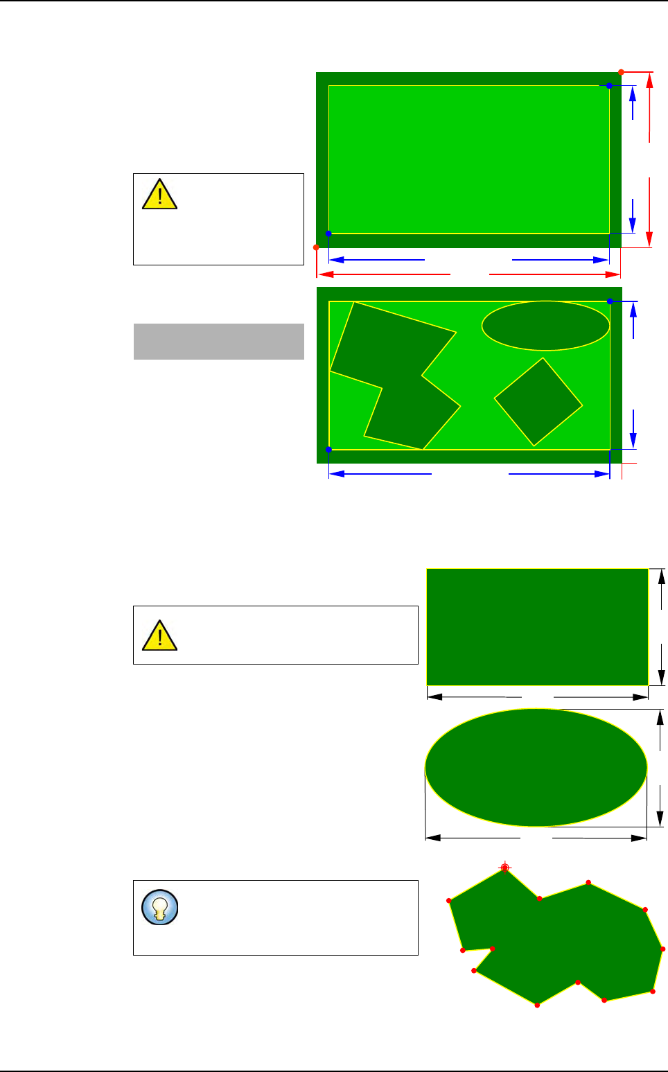
USED_DIM
It is the dimension of the
panel useful zone, whether
single or multiple board,
containing all the compo-
nents to be inspected.
Example
3.1.2.3 Description mode of the panel boards
3 board shapes are used: rectangle, ellipse and polygon:
Rectangle and ellipse shapes are defined by a
width and a height.
Polygon shape is defined by a series of points.
USED_DIM must
always be less
than or equal to
PANEL_DIM.
X Bot-
tom Left
Y Bot-
tom Left
X Top
Right
Y Top
Right
- 78 0 0 45
In Ellipse shape the angle can only be
at 0, 90, 180, 270°.
The origin point (the first point) is the
start of the board drawing and its
rotation axis.
Y dim
X dim
(X0, Y0)
Top Right
Bottom Left
USED_DIM Y
USED_DIM -X
(X0, Y0)
USED_DIM -X
USED_DIM Y
Height
Width
Width
Height
Origin point
.VIS file description
.VIS file
3 - 4 Vision 2007 4.10 User Manual Rev 01
Board parameters
Board shape syntax
The shape is defined in 2 ways:
Board type
3 keywords are used to define the shape:
Rectangle: BOARD,
Ellipse: BOARD_ELLIPSE,
Polygon: BOARD_ POLYGON.
Step and matrix type
A new direction is used to define the shapes: SHAPE
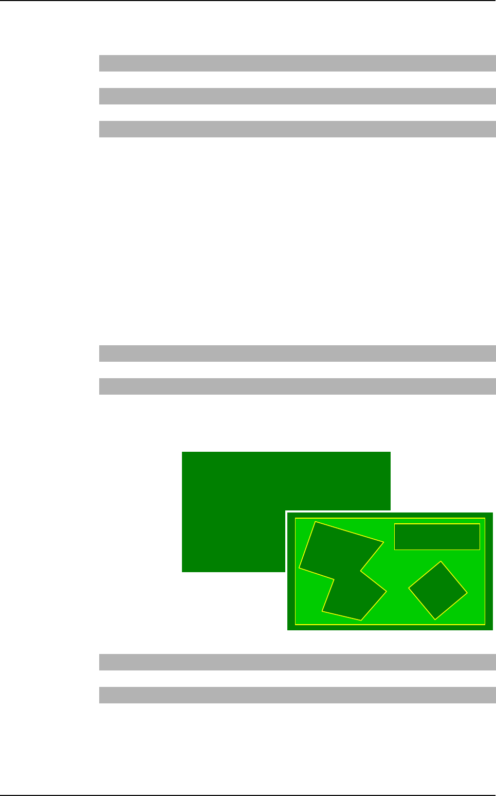
Board arrangement
Board type
It is used to
describe a
panel with one
or several dif-
ferent boards
(shapes, di-
mensions).
The board
name is a num-
ber.
Dimx Board width
Dimy Board height
X, Y Board centrer position (origin point position for polygon board)
Xp, Yp Point position used to describe the polygonal board
Θ
Board angle
Nbpt Number of polygon points
Rectangle SHAPE RECTANGLE
Ellipse SHAPE ELLIPSE
Polygon SHAPE POLYGON Nbpti Xpi1 Ypi1 Xpi2 … XpiN YpiN
Rectangle BOARD nomi Dimxi Dimyi xi yi
Θ
i
Ellipse BOARD_ELLIPSE nomi Dimxi Dimyi xi yi
Θ
i
Polygon BOARD_POLYGON nomi Nbpti Xpi1 Ypi1…XpiN YpiN
.VIS file description