VI User Manual.pdf - 第74页
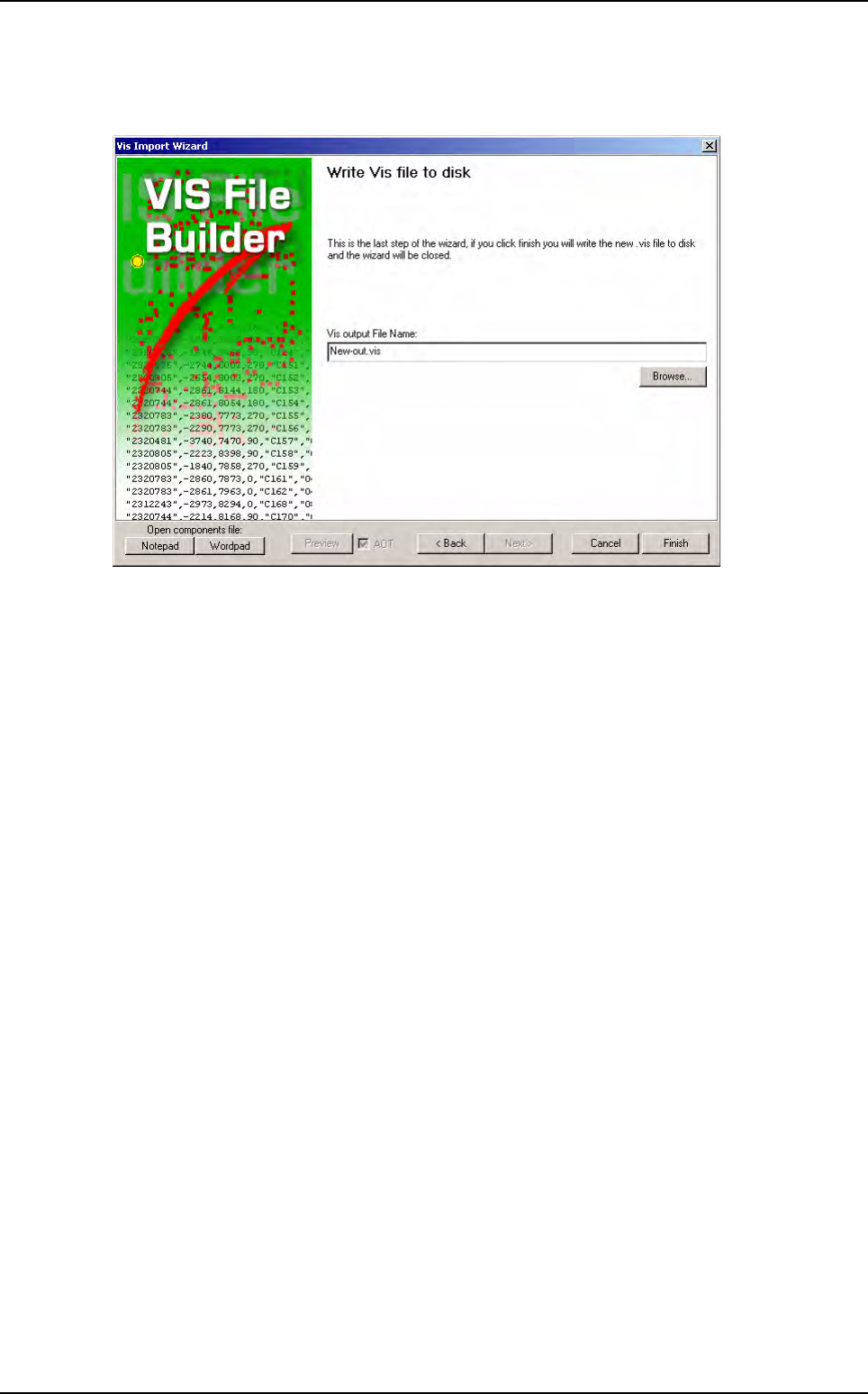
.VIS file 3 - 16 Vision 2007 4.10 User Manual Re v 01 3.2.8 Write .vis file to disk window The last window is to enter the file result name to be saved. Click on Finish and the .vis file is automatically created. .VIS fi…
.VIS file
Vision 2007 4.10 User Manual Rev 01 3 - 15
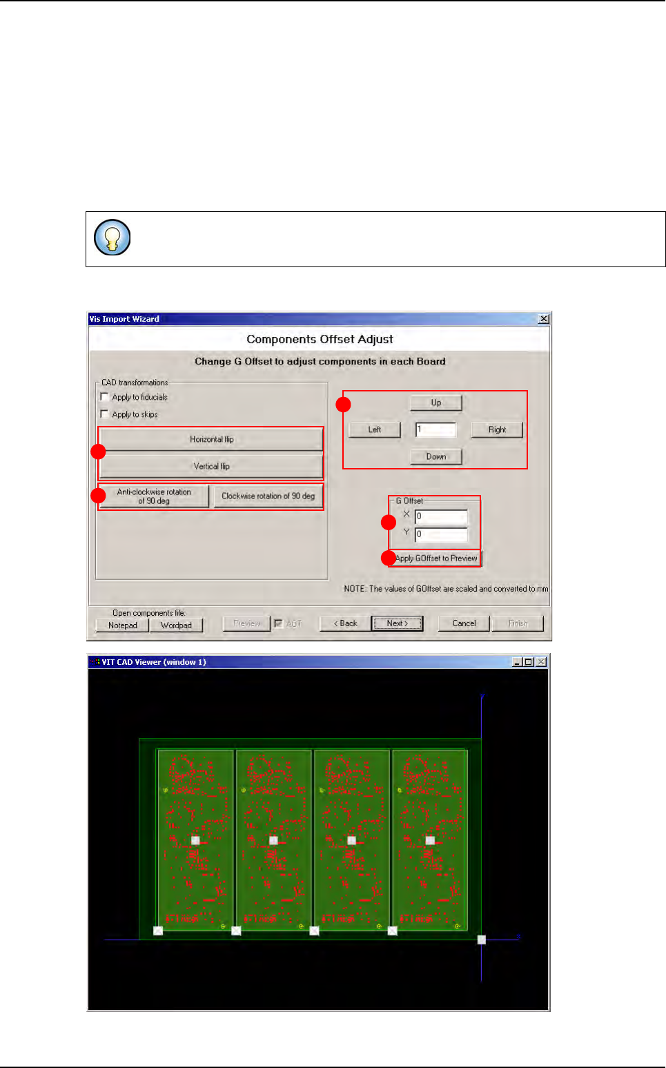
3.2.7 Components offset adjust window
Change the G Offset coordinates (A) and press Apply G Offset to preview button (B) to see
the change directly in the viewer. To adjust the G Offset more precisely, enter the wanted value
in the field (C), and click on Up and Right buttons to increase G Offset values or Down and Left
buttons to reduce it.
In CAD transformations area, click on Horizontal or Vertical flip buttons (D) to invert the po-
sition of components in the .vis file, and click on Anti-clockwise rotation of 90 deg or Clock-
wise rotation of 90 deg buttons (E) to rotate all components in the .vis file.
These transformations could also applied to fiducials and skip.
B
C
A
D
E
.VIS file wizard
.VIS file
3 - 16 Vision 2007 4.10 User Manual Rev 01
3.2.8 Write .vis file to disk window
The last window is to enter the file result name to be saved.
Click on Finish and the .vis file is automatically created.
.VIS file wizard
Vision 2007 4.10 User Manual Rev 01 4 - 1
Chapter 4
.TST file creation
The .tst file is a graphic representation of the panel allowing inspection of the panel by the AOI system.
The .tst file contains:
The information about the size and arrangement of the board.
The CAD coordinates of fiducials and skips.
The CAD coordinates of components and pads.
The position of the acquisition zones and the camera travel for inspection.
The setting of the 5 light levels for each zone.
You can access each component, paste pad or fiducial by clicking directly on it.
It is generated from a .vis file and must be linked to a component library.
Errors on the .vis file can only be detected during generation of the .tst file.
The .tst file is the file to which the lighting parameters and the image treatment (library) are linked for each com-
ponent or type of component.
You can place the .tst file anywhere on your hard disk. However, the .tst file that you intend to use for inspection
in the production mode must be installed in C:\VIT\Data for it to be selected.
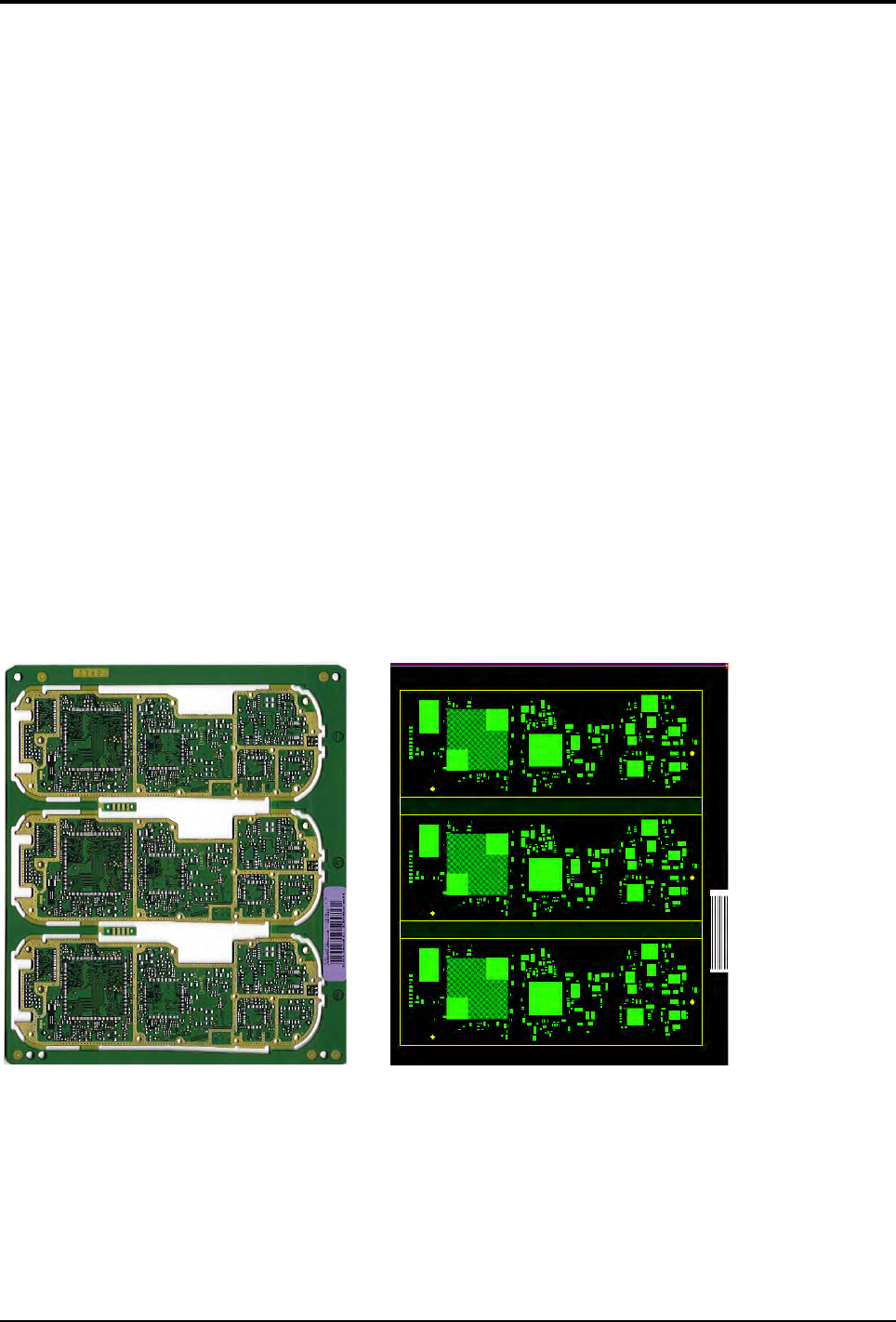
3 boards panel Panel representation