00198705-01_AI_Portalmodularität_SX12_V3_DE_EN.pdf - 第106页
3 Fitting the Gantry 3.6 Final Work 106 Assembly Instructions / Montageanleitung SIPLACE SX1/SX2 V3 Gantry Modularity Portalmodularität 05/2020 3.6 Final Work 3.6.1 Stowing the Gantry Carrier and the Prepared Case Stowin…
3 Fitting the Gantry
3.5 Connecting the Trailing Cable
Assembly Instructions / Montageanleitung SIPLACE SX1/SX2 V3 Gantry Modularity Portalmodularität 05/2020 105
Connections established
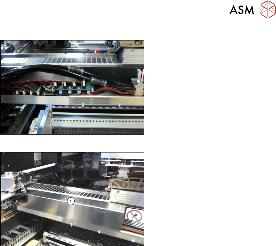
Fig.39: Arranging the connections
This diagram shows the precisely run and
correctly arranged connections.
Fig.40: Fitting the cover
► Fit the cover (1) over the gantry inter-
face.
3 Fitting the Gantry
3.6 Final Work
106 Assembly Instructions / Montageanleitung SIPLACE SX1/SX2 V3 Gantry Modularity Portalmodularität 05/2020
3.6 Final Work
3.6.1 Stowing the Gantry Carrier and the Prepared Case
Stowing the gantry carrier in the transportation crate
► Use the gantry lift to move the gantry carrier into the transportation crate.
► Fix the gantry carrier into place in the transportation crate, with the four fastening screws.
► Release the gantry carrier from the gantry lift and move the gantry lift to one side.
► Place the foam cover for the placement head in the transportation crate.
► Close the front and top cover on the transportation crate.
Placing assembly parts in the "Prepared" case
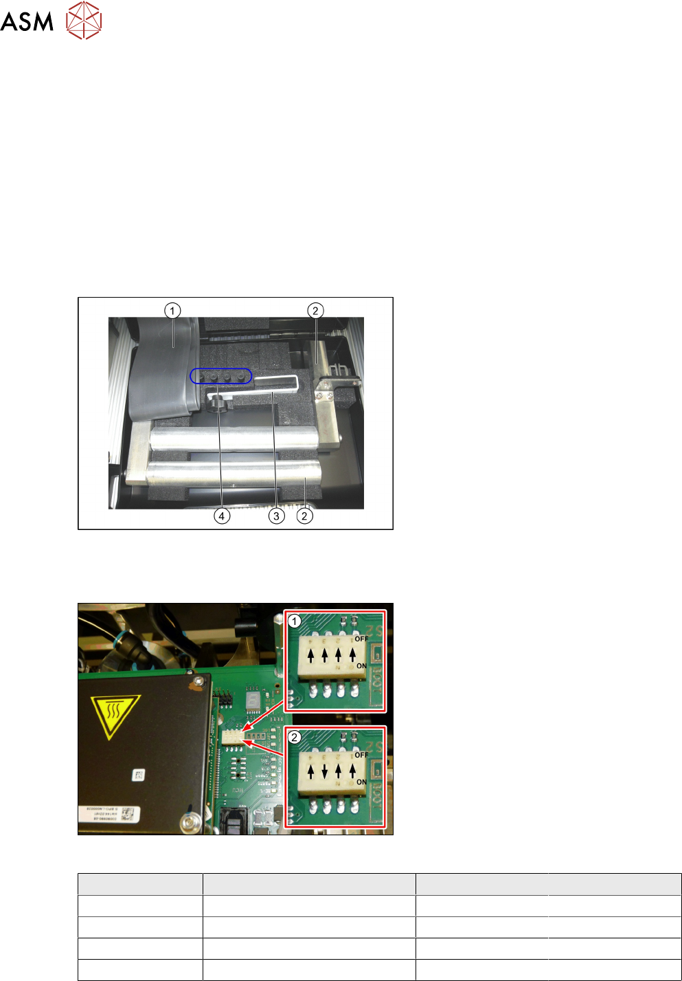
Fig.41: Prepared case
You have removed the following parts which
you will need to dismantle the gantry later
on. Keep these parts in the "Prepared" case:
1. Black plastic foil for trailing cable
2. The long end position buffer.
3. Trailing cable holder with knurled head
screw
4. Two transportation locks for the place-
ment head
●
A green lever as transportation lock for
the gantry
3.6.2 Checking the Gantry Coding
Fig.42: DIP switch gantry encoding for gantry 1 and 2
1. DIP switch for gantry 1
2. DIP switch for gantry 2
► Check the DIP switch for the gantry
coding of the locations on the head in-
terface.
Switch Designation Gantry 1 Gantry 2
1 DC/DC OFF OFF
2 FAN OFF OFF
3 P1 OFF ON
4 P0 OFF OFF
3 Fitting the Gantry
3.6 Final Work
Assembly Instructions / Montageanleitung SIPLACE SX1/SX2 V3 Gantry Modularity Portalmodularität 05/2020 107
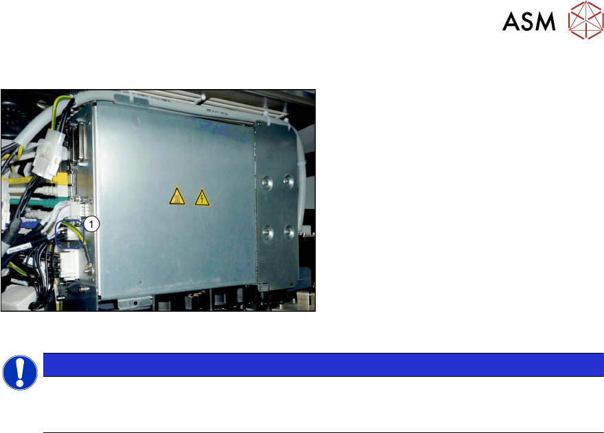
3.6.3 Note MGCU
Fig.43: MGCU supply cable [03068134-xx]
► Please check the connection of the
MGCU power cable with the connector
X1up (1) to ensure a correct start-up of
the machine.
NOTICE
Dismantling a gantry
The connector X1up has to be disconnected from the MGCU, if the gantry is dismantled
later on.
See also
2 5.1 "Overview of MGCU (Rxxxx)" [}123]