00198705-01_AI_Portalmodularität_SX12_V3_DE_EN.pdf - 第109页
3 Fitting the Gantry 3.6 Final Work Assembly Instructions / Montageanleitung SIPLACE SX1/SX2 V3 Gantry Modularity Portalmodularität 05/2020 109 Fig.45: Label BoxPC 1 X1-Vision base interface gantry 1 2 Option: GigE ethe…
3 Fitting the Gantry
3.6 Final Work
108 Assembly Instructions / Montageanleitung SIPLACE SX1/SX2 V3 Gantry Modularity Portalmodularität 05/2020
3.6.4 Checking the Camera Cable
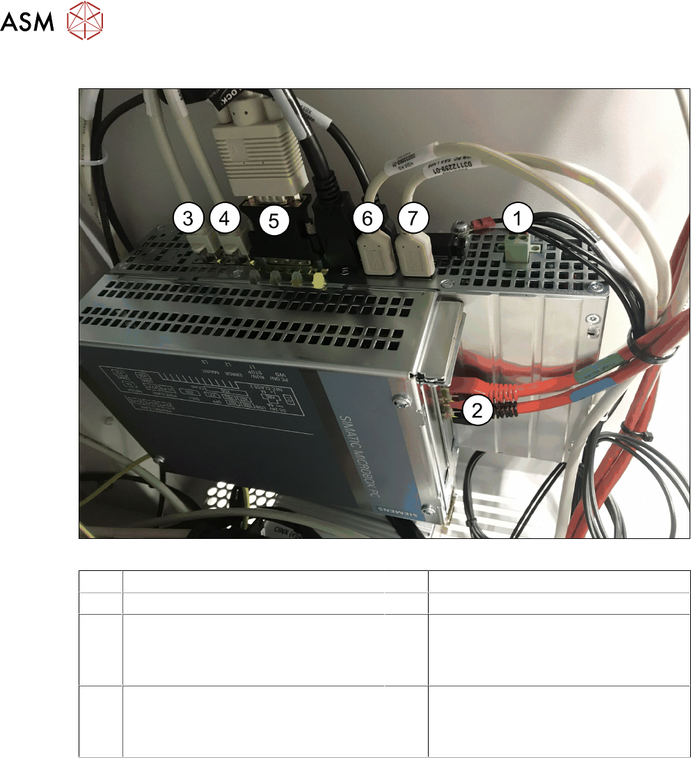
Fig.44: Rear side BoxPC 427D
1 Power supply DC 24V 2 GigE ethernet adapter PCI-E
3 LAN 1: CIN Box 4 LAN 2: connection for line computer
5 DVI/VGA monitor connection
(connection monitor 1)
6 USB 2 – connection for an external DVD
drive
USB 4: X63 - connection for monitor 2
multitouch
7 USB 0: connection for keyboard/touch-
screen (connection to USB hub)
USB 1: X60 connection for monitor 1
multitouch
► Check whether the camera cable is connected to the GigE Ethernet adapter of the box PC.
Pay attention to the correct connections (see labeling on the GigE Ethernet adapter).
3 Fitting the Gantry
3.6 Final Work
Assembly Instructions / Montageanleitung SIPLACE SX1/SX2 V3 Gantry Modularity Portalmodularität 05/2020 109
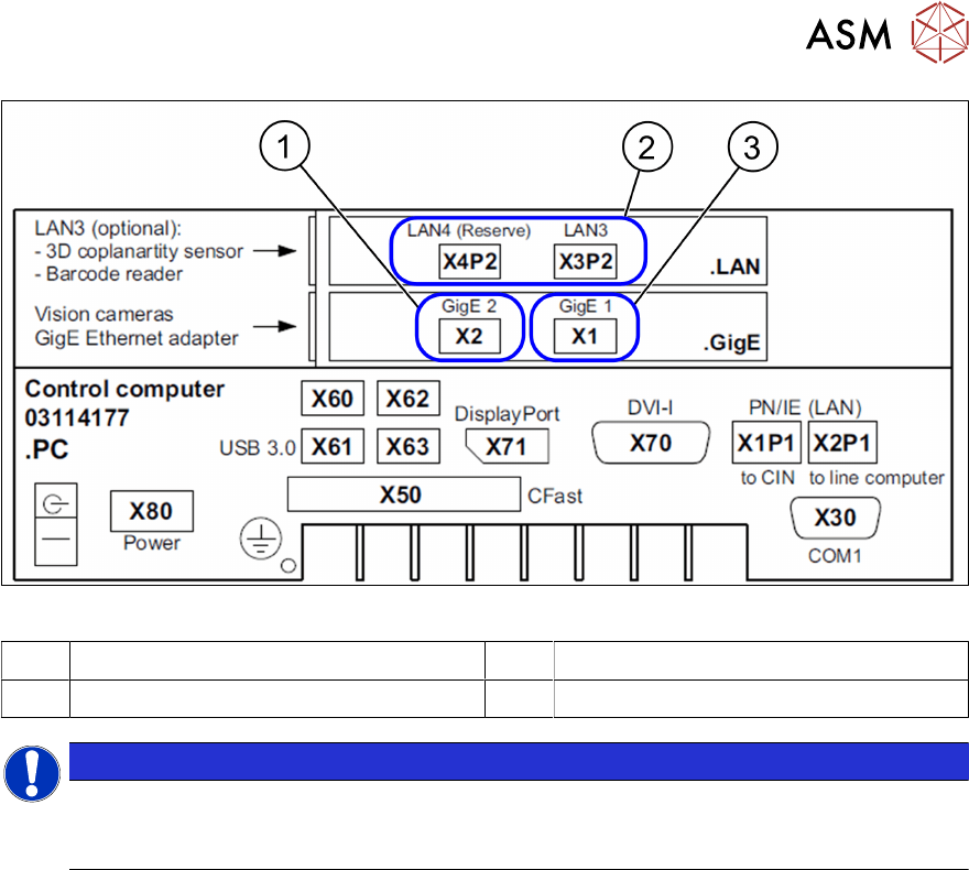
Fig.45: Label BoxPC
1 X1-Vision base interface gantry 1 2 Option: GigE ethernet adapter PCI-E
3 X2 Vision base interface gantry 2
NOTICE
Option
The LAN connections 3 and 4 on the LAN card PCI Express 2xGigabit LAN [03198999‑xx]
are available as an option.
3.6.5 Fitting the Nozzle Changer and Options
Installing the required nozzle changer (head-related)
► See also the assembly instructions "Nozzle Changer - SIPLACE SX-
Series" [DEEN:00196578‑xx].
Fitting the stationary cameras (optional)
► See also the assembly instructions "Stationary Camera SST 25 – SIPLACE X‑SeriesS and
SX V3" [DEEN:00197710‑xx].
Fitting the component reject bin query (optional)
► See also the assembly instructions "Reject Bin Query - for SIPLACE SX1/SX2" [DE
EN:00196615-xx].
Taking into account the component trolley docking unit inner/outer
► See also the service manual "SIPLACE SX1/SX2" [DE:00196496‑xx] [EN:00196497‑xx].
3 Fitting the Gantry
3.6 Final Work
110 Assembly Instructions / Montageanleitung SIPLACE SX1/SX2 V3 Gantry Modularity Portalmodularität 05/2020
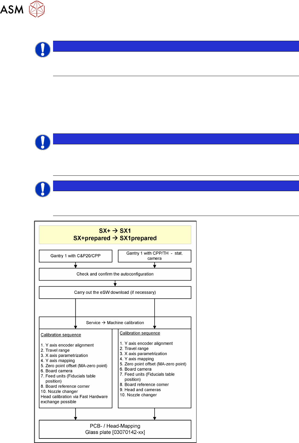
3.6.6 Performing Calibration
NOTICE
Information about mapping
For details of mapping, such as the allocation of mapping plates to machine types, see the
technical information "Information about Mapping" [DE:TI2017‑10D04] [EN:TI2017‑10E04].
Overview
The calibration divides the mapping data and then merges them during the gantry upgrade. In most
cases this means that only a brief calibration procedure needs to be performed (see Fast Hardware
Exchange and flow diagram).
If gantry 1 is fitted, you need to perform PCB/component mapping with the glass plate, irrespective
of the head configuration (gantry 1 is the master gantry).
NOTICE
TwinHead gantry at location 2
If there is a TwinHead gantry fitted at location 2 (gantry 2), the PCB mapping data must be
present. Component mapping can then be performed using the aluminum plate. It is advis-
able to perform a complete PCB/component mapping!
NOTICE
Long Board Option (LBO)
If a gantry is installed on a machine with LBO, this gantry has to be mapped using the Map-
ping with LBO button.
Fig.46: PCB/component mapping