00198705-01_AI_Portalmodularität_SX12_V3_DE_EN.pdf - 第116页
3 Fitting the Gantry 3.7 Checklist 116 Assembly Instructions / Montageanleitung SIPLACE SX1/SX2 V3 Gantry Modularity Portalmodularität 05/2020 3.7 Checklist ► Put this check list in the machine logbook. Gantry fitted (up…
3 Fitting the Gantry
3.6 Final Work
Assembly Instructions / Montageanleitung SIPLACE SX1/SX2 V3 Gantry Modularity Portalmodularität 05/2020 115
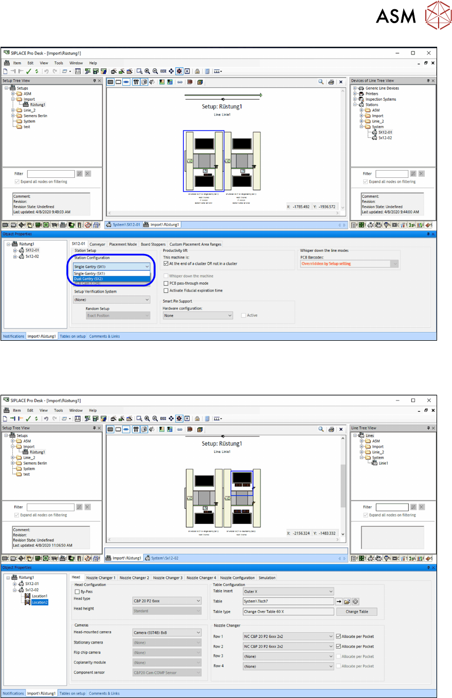
Fig.57: Modification of gantry configuration in the respective setup
Location 2 can be configured afterwards.
The respective head, cameras, nozzles and tables at location 2 has to be edited.
Fig.58: Configuration of head, cameras, nozzles and tables
Recipes / jobs
If existing recipes and jobs should be used in the future then all of them have to be re-optimized
with the new gantry configuration.

3 Fitting the Gantry
3.7 Checklist
116 Assembly Instructions / Montageanleitung SIPLACE SX1/SX2 V3 Gantry Modularity Portalmodularität 05/2020
3.7 Checklist
► Put this check list in the machine logbook.
Gantry fitted (upgrade)
Step Action Who?
1 Gantry fitted? Customer in line with assembly
guide
2 Is the CPP head fitted in the correct position? Customer in line with assembly
guide
3 Are the correct end position buffers fitted? Customer in line with assembly
guide
4 Has the trailing cable been fitted correctly? Customer in line with assembly
guide
5 Does the trailing cable run parallel? Customer in line with assembly
guide
6 Is the gantry coding correct? Customer in line with assembly
guide
7 Is the stationary camera (optional) fitted? Customer in line with assembly
guide
8 Are the camera connections connected to Box PC? Customer in line with assembly
guide
9 Has the nozzle changer been fitted? Customer in line with assembly
guide
10 Is the reject bin fitted? Customer in line with assembly
guide
11 Have all tools been removed from the machine? Customer in line with assembly
guide
12 Are the doors screwed? Customer in line with assembly
guide
13 Is the machine switched on and ready for operation? Customer in line with assembly
guide
14 Have all calibration steps been performed? Customer in line with assembly
guide
Date Signature

4 Dismantling a Gantry
Assembly Instructions / Montageanleitung SIPLACE SX1/SX2 V3 Gantry Modularity Portalmodularität 05/2020 117
4 Dismantling a Gantry
NOTICE
Describing the correct packaging on an SX gantry
Please also observe the technical information "Description of correct packaging for an SX
gantry" [DE:TI2013‑05D06] [EN:TI2013‑05E06].
1. Get the transportation crate with gantry carrier and "Prepared" case ready.
– Dummy plugs for hoses
– Black plastic foil for trailing cable.
– Long end position buffer
– Trailing cable holder and knurled head screw
– Loose lever for transportation lock
2. Remove the gantry carrier from the transportation case with the gantry lift and lock into place.
3. Remove the keyboard and open the two side covers.
4. Push the gantry into a suitable working position in the machine.
5. Disconnect the trailing cable from the gantry interface of the X and Y axis (flat ribbon cable
and hoses).
6. Close the four hoses on the trailing cable with the dummy plugs.
7. Dismantle the trailing cable fixture from the Y sensor module holder with the two hexagon
spacer bolts.
8. Pack the trailing cable with the black foil.
9. Fit the trailing cable holder and the trailing cable.
10. Move the placement head into the center of the gantry. This ensures that the load is distrib-
uted evenly.
11. Fit the two transportation locks for the placement head. The head must be in the center of the
gantry.
12. Move the gantry lift with locked gantry carrier up to the docking unit of the machine.
13. Remove both end position buffers.
14. Using the docking hooks, hook the gantry carrier into the openings of the docking unit.
15. Push the gantry onto the gantry carrier and make sure that the tilt guard engages into place!
16. Lift the gantry lift with the gantry carrier and the gantry out of the docking unit and move it out
of the machine.
17. Attach the three transportation locks for the gantry to the gantry carrier! Only transport the
gantry with the gantry carrier when all transportation locks are in place! Do not move the
gantry with the gantry carrier over long distances. The transportation crate must be in the im-
mediate vicinity of the machine.
18. Open the transportation crate at the top and front. The four screws are secured with the chain
at 4 points.
19. Lift the gantry with the gantry carrier into the crate and tighten the four screws.
20. Unlock the gantry carrier from the gantry lift and move the lift away.
21. Place the foam cover over the placement head and close the crate.