00198705-01_AI_Portalmodularität_SX12_V3_DE_EN.pdf - 第118页
4 Dismantling a Gantry 4.1 Final work on the machine 118 Assembly Instructions / Montageanleitung SIPLACE SX1/SX2 V3 Gantry Modularity Portalmodularität 05/2020 4.1 Final work on the machine ► At location 2 only : fit th…

4 Dismantling a Gantry
Assembly Instructions / Montageanleitung SIPLACE SX1/SX2 V3 Gantry Modularity Portalmodularität 05/2020 117
4 Dismantling a Gantry
NOTICE
Describing the correct packaging on an SX gantry
Please also observe the technical information "Description of correct packaging for an SX
gantry" [DE:TI2013‑05D06] [EN:TI2013‑05E06].
1. Get the transportation crate with gantry carrier and "Prepared" case ready.
– Dummy plugs for hoses
– Black plastic foil for trailing cable.
– Long end position buffer
– Trailing cable holder and knurled head screw
– Loose lever for transportation lock
2. Remove the gantry carrier from the transportation case with the gantry lift and lock into place.
3. Remove the keyboard and open the two side covers.
4. Push the gantry into a suitable working position in the machine.
5. Disconnect the trailing cable from the gantry interface of the X and Y axis (flat ribbon cable
and hoses).
6. Close the four hoses on the trailing cable with the dummy plugs.
7. Dismantle the trailing cable fixture from the Y sensor module holder with the two hexagon
spacer bolts.
8. Pack the trailing cable with the black foil.
9. Fit the trailing cable holder and the trailing cable.
10. Move the placement head into the center of the gantry. This ensures that the load is distrib-
uted evenly.
11. Fit the two transportation locks for the placement head. The head must be in the center of the
gantry.
12. Move the gantry lift with locked gantry carrier up to the docking unit of the machine.
13. Remove both end position buffers.
14. Using the docking hooks, hook the gantry carrier into the openings of the docking unit.
15. Push the gantry onto the gantry carrier and make sure that the tilt guard engages into place!
16. Lift the gantry lift with the gantry carrier and the gantry out of the docking unit and move it out
of the machine.
17. Attach the three transportation locks for the gantry to the gantry carrier! Only transport the
gantry with the gantry carrier when all transportation locks are in place! Do not move the
gantry with the gantry carrier over long distances. The transportation crate must be in the im-
mediate vicinity of the machine.
18. Open the transportation crate at the top and front. The four screws are secured with the chain
at 4 points.
19. Lift the gantry with the gantry carrier into the crate and tighten the four screws.
20. Unlock the gantry carrier from the gantry lift and move the lift away.
21. Place the foam cover over the placement head and close the crate.
4 Dismantling a Gantry
4.1 Final work on the machine
118 Assembly Instructions / Montageanleitung SIPLACE SX1/SX2 V3 Gantry Modularity Portalmodularität 05/2020
4.1 Final work on the machine
► At location 2 only: fit the long end position buffer if the gantry has been removed. Use a
torque wrench to tighten to 14Nm. Take a look at the buffer monitoring function! The safety
switch for buffer monitoring function must engage in the Schmersal switch.
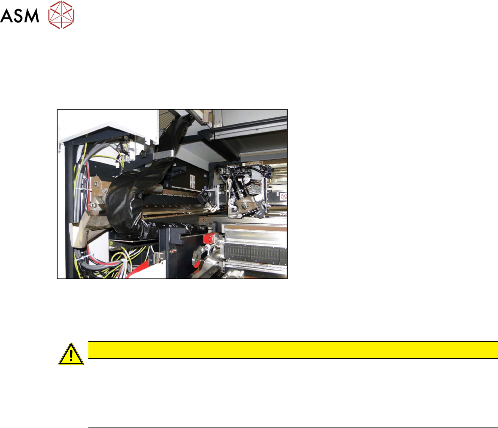
Fig.59: Trailing cable on bracketcable
► Fit the trailing cable to the holder next
to the MGCU.
► Close the two side doors again.
► Calibrate (see below)
CAUTION
Check, stationary camera, nozzle changer
► Check whether gantry 1 can move to location 2 unhindered and whether it can also
reach the table pickup position.
► In certain configurations, you need to dismantle the stationary camera and the second
nozzle changer row and then move the table from the outer to the inner position.