00198705-01_AI_Portalmodularität_SX12_V3_DE_EN.pdf - 第68页
68 Assembly Instructions / Montageanleitung SIPLACE SX1/SX2 V3 Gantry Modularity Portalmodularität 05/2020 Contents 3.3.3 Locking and Transporting the Gantry Carrier .. 97 3.3.4 Transportation Locks and Tilt Guard ..…

67Assembly Instructions / Montageanleitung SIPLACE SX1/SX2 V3 Gantry Modularity Portalmodularität 05/2020
Contents
Contents
1 Introduction.. 69
1.1 Safety instructions.. 69
1.1.1 Conventions for the use of safety instructions and symbols.. 69
1.1.2 Safety instructions for working with strong magnetic fields.. 70
1.1.3 Safety instructions for the power supply.. 70
1.1.4 Safety instructions for the compressed air supply.. 72
1.1.5 Safety instructions for work on the cutting device.. 72
1.1.6 Safety instructions for the gantry.. 72
1.2 Preparatory work..... 73
1.3 Other instructions.. 75
1.3.1 Environmentally-friendly disposal of materials and components.. 75
1.3.2 Use of original accessories and spare parts.. 75
1.3.3 ESD guidelines.. 75
1.3.3.1 What does ESD mean?.. 75
1.3.3.2 Important measures to protect against static charging.. 75
1.3.3.3 Handling ESD modules.. 75
1.3.3.4 Measurements and modifications to ESD modules.. 76
1.3.3.5 Dispatching ESD modules.. 76
1.3.4 Release History.. 76
1.4 Abbreviations.. 76
2 Brief Description.. 77
2.1 Overview.. 77
2.1.1 Machine Variants.. 77
2.1.2 Head Configuration.. 77
2.1.3 Overview of "Fast Gantry Modularity".. 80
2.1.4 Configurations.. 82
2.1.4.1 Table Positions.. 82
2.1.4.2 Stationary Cameras.. 83
2.1.5 Additional Work.. 85
2.1.5.1 Buffer Stopper.. 85
2.1.5.2 Empty Tape Duct Intermediate Plate.. 86
2.2 Scope of Delivery.. 87
2.2.1 SIPLACE C&P20P2 head.. 88
2.2.2 SIPLACE Twin P&P.. 88
2.2.3 SIPLACE CPP head.. 88
2.2.4 Gantry.. 89
2.2.5 Gantry carrier plate for SIPLACE SX1/SX2 [03012160-xx].. 89
2.3 Tools and Equipment Required.. 89
3 Fitting the Gantry.. 91
3.1 Requirements.. 91
3.1.1 SIPLACE SX "Prepared".. 91
3.2 Preparations at the Machine.. 91
3.2.1 Removing the End Position Buffer.. 92
3.2.2 Preparing the Trailing Cable.. 92
3.3 Gantry Preparations.. 94
3.3.1 The Gantry Lift.. 94
3.3.2 Unpacking the Gantry.. 96

68 Assembly Instructions / Montageanleitung SIPLACE SX1/SX2 V3 Gantry Modularity Portalmodularität 05/2020
Contents
3.3.3 Locking and Transporting the Gantry Carrier.. 97
3.3.4 Transportation Locks and Tilt Guard.. 99
3.4 Installing the Gantry.. 100
3.4.1 Fitting the Short End Position Buffer.. 103
3.5 Connecting the Trailing Cable.. 103
3.6 Final Work.. 106
3.6.1 Stowing the Gantry Carrier and the Prepared Case.. 106
3.6.2 Checking the Gantry Coding.. 106
3.6.3 Note MGCU.. 107
3.6.4 Checking the Camera Cable.. 108
3.6.5 Fitting the Nozzle Changer and Options.. 109
3.6.6 Performing Calibration.. 110
3.6.6.1 eSW Download (SW 70x).. 112
3.6.7 Modifications in SIPLACE Pro.. 114
3.7 Checklist.. 116
4 Dismantling a Gantry.. 117
4.1 Final work on the machine.. 118
4.2 Performing Calibration.. 119
4.2.1 eSW Download (SW 70x).. 120
4.3 Checklist.. 122
5 Annex.. 123
5.1 Overview of MGCU (Rxxxx).. 123
1 Introduction
1.1 Safety instructions
Assembly Instructions / Montageanleitung SIPLACE SX1/SX2 V3 Gantry Modularity Portalmodularität 05/2020 69
1 Introduction
This manual describes the gantry exchange procedure for SIPLACE® SX1/SX2 V3 machines from
serial number R0001.
1.1 Safety instructions
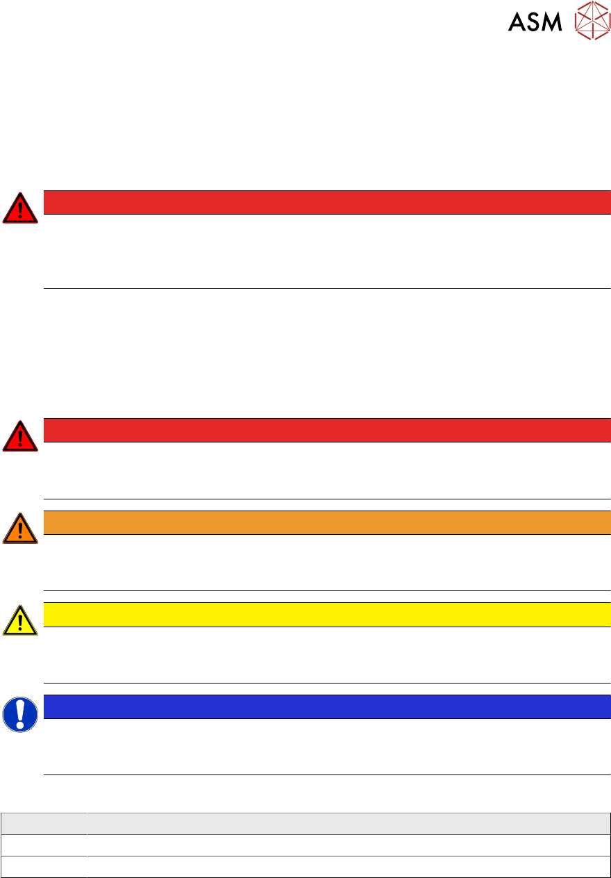
DANGER
Nonobservance of these safety instructions may cause injury to personnel and dam-
age to the machine!
► Please observe the safety instructions in the user manual of the relevant machine
for all work!
1.1.1 Conventions for the use of safety instructions and symbols
Safety instructions
This manual contains notes that must be observed to guarantee your personal safety and to avoid
damage to equipment. These notes are highlighted by warning triangles and are indicated as fol-
lows according to the level of risk:
DANGER
Definition
For the purposes of this manual, this indicates that fatal or severe injuries or considerable
damage to property will occur if this hazard warning is not observed.
WARNING
Definition
For the purposes of this manual, this indicates that fatal or severe injuries or considerable
damage to equipment may occur if these warning instructions are not followed.
CAUTION
Definition
For the purposes of this manual, this indicates that minor injuries or damage to property
may occur if this caution is not observed.
NOTICE
Definition
For the purposes of this manual, this note provides information about the product or indic-
ates a part of the manual that requires particular attention.
Symbols
Example Description
Next This typeface marks controls and interface elements in the software.
► This symbol indicates actions that have to be performed by the operator.