00198705-01_AI_Portalmodularität_SX12_V3_DE_EN.pdf - 第80页
2 Brief Description 2.1 Overview 80 Assembly Instructions / Montageanleitung SIPLACE SX1/SX2 V3 Gantry Modularity Portalmodularität 05/2020 2.1.3 Overview of "Fast Gantry Modularity" The following flow diagrams…

2 Brief Description
2.1 Overview
Assembly Instructions / Montageanleitung SIPLACE SX1/SX2 V3 Gantry Modularity Portalmodularität 05/2020 79
SIPLACE SX1 prepared
●
Machine with one gantry
●
Prepared for a gantry upgrade to a SX2
Head configuration SIPLACE SX1 prepared
Gantry 1 C&P20
P2
CPP_L CPP_L C&P20
P2
CPP_H with
1)
stat. camera
CPP_H
with
1)
/
without stat.
camera
TH
2)
TH
2)
Gantry 2 C&P20
P2
CPP_L C&P20
P2
CPP_L CPP_H
with
1)
/
without stat.
camera
TH
2)
CPP_H TH
2)
SIPLACE SX2
●
Machine with two gantries
●
This machine can be downgraded to a SX1 prepared. It will then be prepared for a gantry
upgrade to a SX2.
Head configuration SIPLACE SX2
Gantry 1 C&P20
P2
CPP_L CPP_L C&P20
P2
CPP_H with
1)
stat. camera
CPP_H
with
1)
/
without stat.
camera
TH
2)
TH
2)
Gantry 2 C&P20
P2
CPP_L C&P20
P2
CPP_L CPP_H
with
1)
/
without stat.
camera
TH
2)
CPP_H TH
2)
1)
A CPP and a stationary camera require the high position (CPP_H) and the outer table position.
2)
A TH and a stationary camera require the outer table position.
NOTICE
40 mm gantry with VHF
A 40mm gantry with VHF can be retrofitted. See also the assembling instructions
"SIPLACE SX1/SX2 V3 Reconfiguration kit Twin VHF with gantry" [00198783-xx]
2 Brief Description
2.1 Overview
80 Assembly Instructions / Montageanleitung SIPLACE SX1/SX2 V3 Gantry Modularity Portalmodularität 05/2020
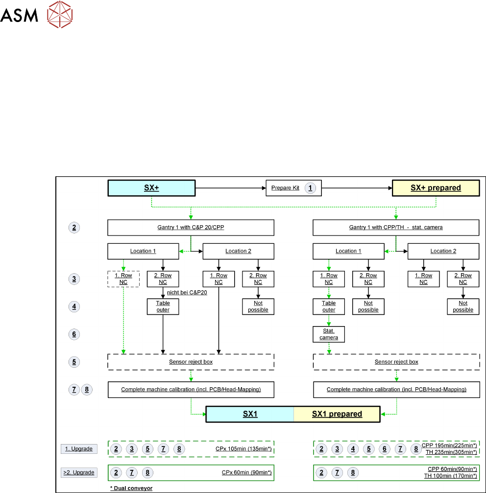
2.1.3 Overview of "Fast Gantry Modularity"
The following flow diagrams show the key steps to be performed. The exact steps required depend
on the individual machine type.
A differentiation needs to be made between the first and any later upgrades (2. to n.), in relation to
the Fast Gantry Modularity function, as additional work is required for the first upgrade (e.g. in-
stalling the nozzle changer, reject bin and sensors). This additional work does not need to be re-
peated for later upgrades, as these parts can remain in the machine during the gantry download.
The lowest time needed for work, approx. 30min, is incurred during upgrade of an SX1 prepared
machine to an SX2, which is equipped with a C&P20 or CPP head for the second gantry. This is
shown by the broken lines in the flow diagrams.
Fig.5: Upgrade of SX+ and SX+ prepared
2 Brief Description
2.1 Overview
Assembly Instructions / Montageanleitung SIPLACE SX1/SX2 V3 Gantry Modularity Portalmodularität 05/2020 81
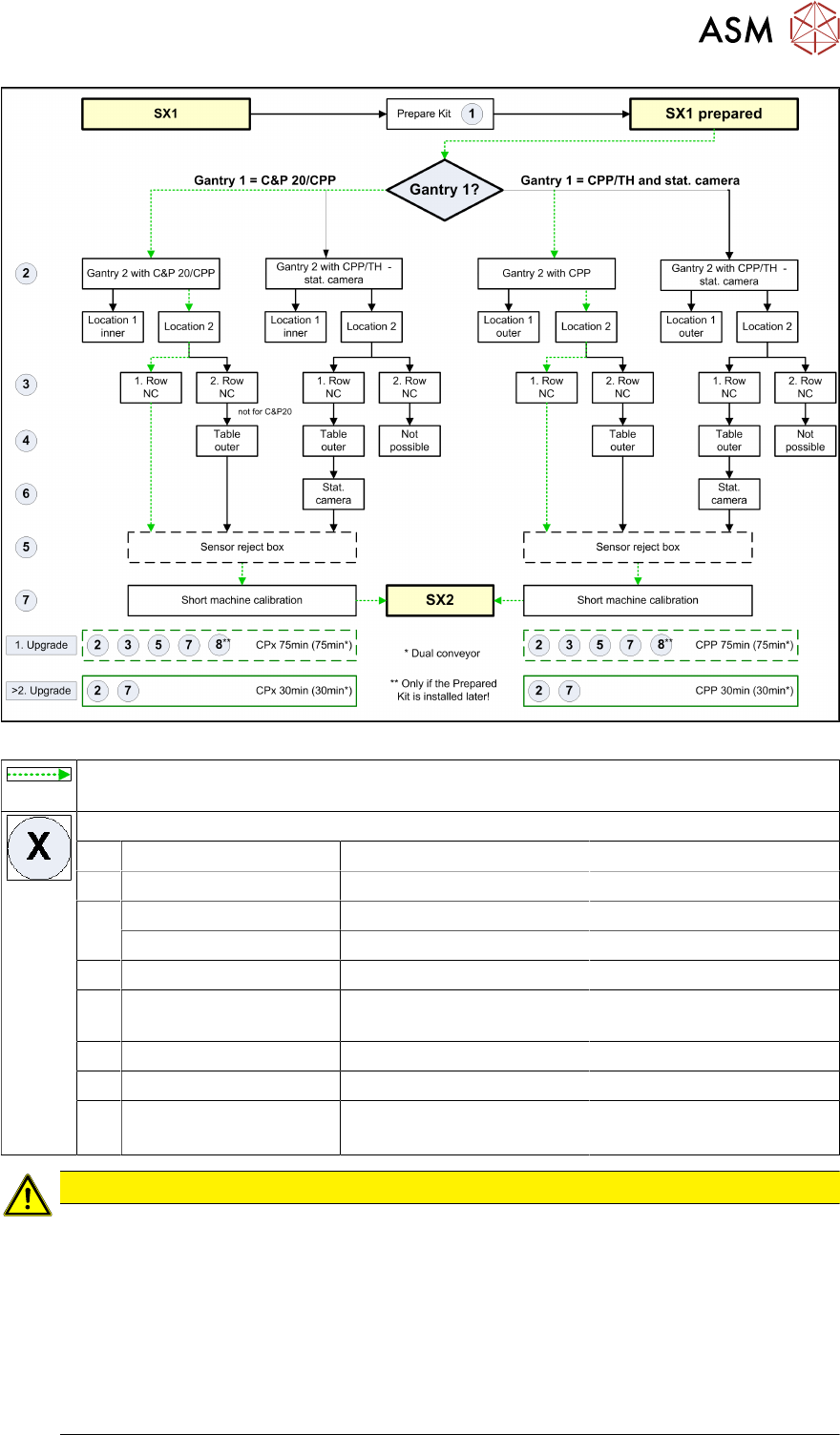
Fig.6: Upgrade of SX1 and SX1 prepared
These arrows show the gantry upgrade procedure involving the least work for the relev-
ant machine types.
Work to be performed:
1 Prepared kit 180 min SIPLACE Service
2 Rerail gantry 15 min Customer
3 NC row 1 30 min Customer
NC row 2 20 min Customer
4 Outer table position 60 min SIPLACE Service, customer
5 Reject bin sensors (op-
tional)
15 min Customer
6 Stationary cameras 30 min SIPLACE Service, customer
7 Calibrating the machine 15 min Customer
8 PCB/component map-
ping
30 min per conveyor lane CPx
70 min per conveyor lane TH
SIPLACE Service, customer
CAUTION
PCB/component mapping
If a SX1 prepared or a prepared kit is installed at the customer site and a second gantry is
mounted for the first time, a complete PCB/component mapping for the 2nd gantry is required.
This is necessary because of the extended Y-traversing path and the Y-drive motor lying on
the other side of the machine.
Component mapping is always required for a gantry upgrade with Twin Head (VHF TH).
Recommendation: if gantries are replaced, component mapping should be performed for
process reliability (accuracy) reasons.
(See 4.2 "Performing Calibration" [}119])