00198705-01_AI_Portalmodularität_SX12_V3_DE_EN.pdf - 第90页
2 Brief Description 2.3 Tools and Equipment Required 90 Assembly Instructions / Montageanleitung SIPLACE SX1/SX2 V3 Gantry Modularity Portalmodularität 05/2020
2 Brief Description
2.3 Tools and Equipment Required
Assembly Instructions / Montageanleitung SIPLACE SX1/SX2 V3 Gantry Modularity Portalmodularität 05/2020 89
2.2.4 Gantry
Designation Item no.
GR Gantry SX V3 03220742-xx
Gantry carrier SX1/2 03064450-xx
Transportation crate for SX gantry system 03079586-xx
2.2.5 Gantry carrier plate for SIPLACE SX1/SX2 [03012160-xx]
Amount Designation Item No.
1 Holder 03068900-xx
2 Anchor 03068901-xx
1 Distance plate 03016437-xx
2 DIN 6912-M8 x 40-A2-70 03046168-xx
8 DIN 125-A 8.4-140HV-A2 03045649-xx
8 DIN912-M8 x 20-A2-70 03045111-xx
2.3 Tools and Equipment Required
●
Gantry lift
WARNING
Installation
The installation can be performed manually, although we do recommend using a gantry lift
for safety purposes.
●
Torque wrench (2–25Nm) [00376625‑xx]
●
Loctite 241 [02101037-xx]
●
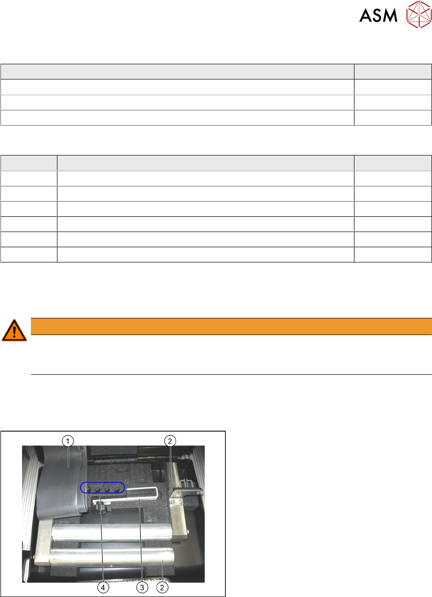
Prepared case (plastic case with foam insert) containing the following:
Prepared case
The case is configured differently depending
on the machine type.
1. Trailing cable protective foil
2. Buffer stop (2x)
3. Trailing cable mount
4. Pneumatic hose plug (4x)

2 Brief Description
2.3 Tools and Equipment Required
90 Assembly Instructions / Montageanleitung SIPLACE SX1/SX2 V3 Gantry Modularity Portalmodularität 05/2020
3 Fitting the Gantry
3.1 Requirements
Assembly Instructions / Montageanleitung SIPLACE SX1/SX2 V3 Gantry Modularity Portalmodularität 05/2020 91
3 Fitting the Gantry
NOTICE
This manual describes the upgrading of gantry 2 at location 2. The assembly of gantry 1 is
identical.
NOTICE
When upgrading gantry 1 (master gantry) at location 1, board and component mapping
must be performed after the assembly.
3.1 Requirements
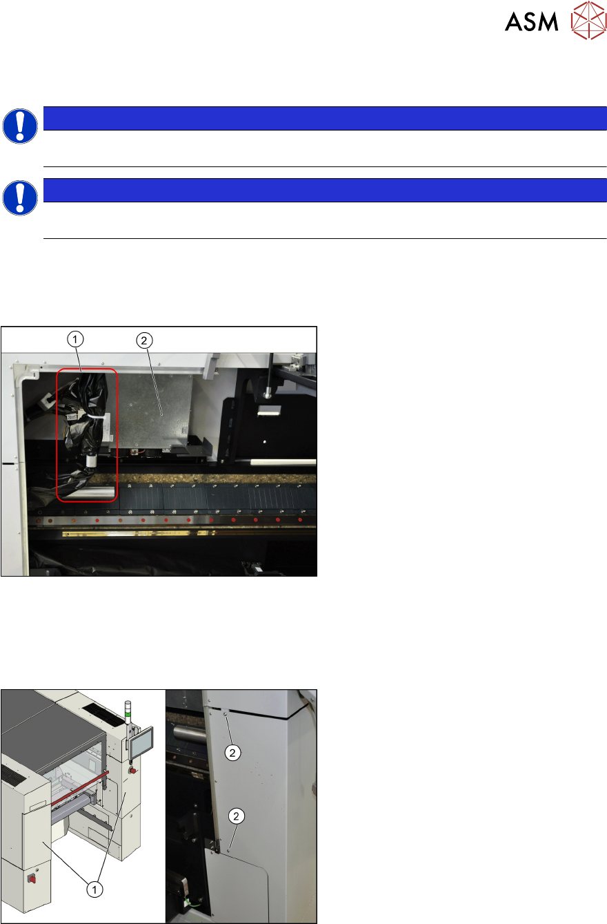
3.1.1 SIPLACE SX "Prepared"
Fig.11: Trailing cable and main axes
The SIPLACE SX must be in the delivery
state "Prepared".
This can be recognized by the presence of a
trailing cable (1) and the control unit for the
main axes (Gantry Control Unit (2)). This ap-
plies for the SIPLACE SX+ machine, in or-
der to retrofit gantry 1 at location 1 or for the
SIPLACE SX1 "Prepared", in order to retrofit
gantry 2 at location 2.
The trailing cable is packed in a black plastic
case and is fixed at the side (1).
If this is not the case, your machine will
need to be retrofitted accordingly. Contact
your SIPLACE Service team for details.
3.2 Preparations at the Machine
Overview
Fig.12: Overview of protective cover
► Open the protective cover at location 2
and move the component trolley out of
the machine.
► Loosen the two screws (2) fastening
the side covers (1) on the right and left.
► Open the two covers (1).