'操作说明 Hotflow THREE_26_zh.pdf - 第473页
1. FOR YOUR SAFETY ENGLISH T ranslation of the original 16 451820.66.03_EN 2020-05-05
Translation of the original ENGLISH 1. FOR YOUR SAFETY
451820.66.03_EN
2020-05-05
15
1.11 Residual energy and residual risks
1.11.1 Residual energy
Even if all safety notes are observed, the following residual energy can still present a hazard:
• Rotational energy of the fan
• Hot surfaces on machine parts
• Electrical voltage in the control cabinet despite a deactivated main switch
• Refrigerant circuit under pressure
1.11.2 Residual risks
Electrical/mechanical
No risk exists if all safety regulations are observed.
1.12 Notes on minimizing noise and vibrations
Noise
Noise pollution due to airborne noise emissions can be minimised as follows:
• Select an installation location that is not in the vicinity of workplaces and do not direct
the air intake/outlet side towards a workplace.
Vibration
The vibrations caused by the compressor are largely decoupled by the frame.
To further reduce the effect of vibrations, optional vibration-damping levelling feet can be fitted to the
cooling unit.
(See chapter 15.8 "Accessories")

1. FOR YOUR SAFETY ENGLISH Translation of the original
16
451820.66.03_EN
2020-05-05
Translation of the original ENGLISH 2. DESCRIPTION OF THE COOLING UNIT
451820.66.03_EN
2020-05-05
17
2. DESCRIPTION OF THE COOLING UNIT
The cooling unit is a ready-to-use system with refrigerant circuit and water circuit complete with all
fittings and control devices required for automatic operation.
The heat extracted from the water is released into the surrounding air via the refrigerant circuit using
the fans.
2.1 Refrigerant circuit
The refrigerant circuit is a closed system in which the refrigerant is circulated as the working
medium.
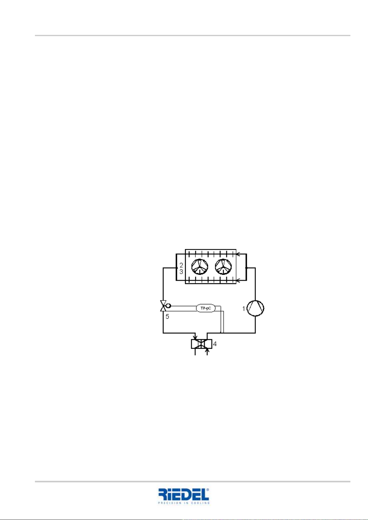
The water heated by the consumer is re-cooled in the evaporator (4). During this process, the liquid
refrigerant is routed in the opposite direction to the water flow. As a result of absorbing the waste
heat from the consumer’s cooling water, the refrigerant evaporates.
The refrigerant, now in gaseous form, is drawn in and compressed by the compressor (1) (pressure
and temperature increase). The energy from the compressor is also taken up by the refrigerant and
released into the surrounding air as waste heat by the liquefiers (2) with the help of the fan (3).
As a result, the refrigerant is liquefied and passes via the liquid receiver, isolating valve, filter dryer
and sight glass in front of the expansion valve (5). This allows liquid refrigerant into the evaporator
depending on the temperature.
The circuit is now closed.
The refrigeration capacity is regulated by switching the compressors on and off.
Block flow diagram, refrigerant circuit