'操作说明 Hotflow THREE_26_zh.pdf - 第493页
7. COMMISSIONING ENGLISH Translation of the original 36 451820.66.03_EN 2020-05-05 In general, the pressure should remain stable at around 1.5 bar during pump operation. If this is not the case, air is still present in t…
Translation of the original ENGLISH 7. COMMISSIONING
451820.66.03_EN
2020-05-05
35
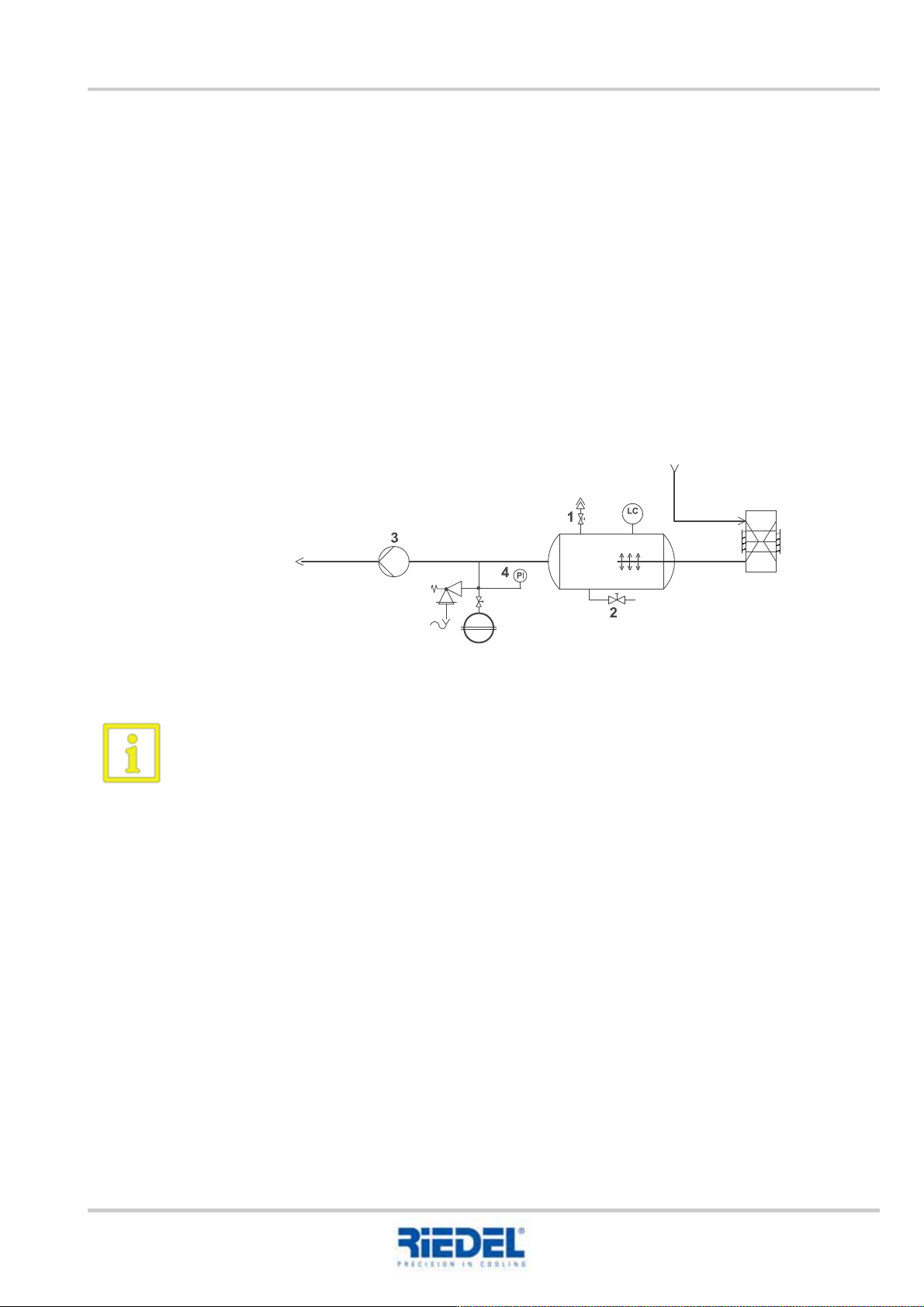
7.1.4 Commissioning of atmospherically closed systems
Tasks to be carried out:
Example figure
When using a water-glycol mixture and in the case of insufficient water pressure in the
public water system, an additional filling pump must be used.
1. Switch mains disconnecting device (main switch) to position "0"
2. Ensure all motor protection switches, control switches and circuit breakers are in
position -0-
3. Remove covering panels on the service side
4. Open all bleeder valves (1)
5. Fit a bleeder valve externally at the highest point and open it
6. Slowly fill the system from the public water supply via the fill and drain valve (2) on the
tank.
7. Close the non-automatic bleeder valve (1 and external) as soon as water spills out
8. Continue to fill the system until the pressure gauge (4) indicates a fill pressure of 1 to
1.5 bar
9. Purge the pump (3) via the bleeder screw on the pump housing
10. Switch fuses and motor protection switches for pump and fan to position "1"
(see wiring diagram)
11. Switch on pump (3) via mains disconnecting device, control switch in position -1-
Check the specified direction of rotation of the pump (see rotation direction arrow on drive
motor)
12. If the direction of rotation of the pump is incorrect, disconnect the cooling unit from the
power and swap 2 phases of the main connection cable
13. Perform a visual check of the entire water circuit for leaks
14. During pump operation, the pressure on the pressure gauge (4) must not be less than
0.5 bar, otherwise the re-filling process must be repeated.

7. COMMISSIONING ENGLISH Translation of the original
36
451820.66.03_EN
2020-05-05
In general, the pressure should remain stable at around 1.5 bar during pump operation. If this
is not the case, air is still present in the water circuit and the system must be purged again
via the bleeder valves until water escapes.
Installing the expansion vessel
The expansion vessel should ideally be installed close to the pump on the suction side. In front of
the vessel, a shut-off device must be installed that can be secured against unintentional closing
(cap valve with seal lock and bleeder valve). The pressure distribution in the system is dictated by
the chosen installation location.
Primary pressure – setting p
0
The gas primary pressure p
0
must be adapted to the local conditions and is based on the static
system height (p
st
) as well as an addition of approx. 0.2 bar at normal room temperature.
Example: system height 8 m (= 0.8 bar), p
0
= 1 bar.
Fill pressure p
F
Inserting the water seal V
v
with a fill pressure which lies 0.3 to 0.5 bar above the gas primary
pressure p
0
and purging the system in a cold state causes the fill pressure p
F
to form.
Example: p
0
= 1 bar, p
F
= 1.3 ... 1.5 bar.
The fill pressure depends on the temperature of the filled medium: for each 10K increase in
temperature, the fill pressure must be reduced by 0.2 bar.
Final pressure p
e
Heating the system to the maximum system temperature causes the expansion volume V
e
to be
applied in the expansion vessel. The system pressure and the gas reserve pressure rise to the
same pressure (final pressure p
e
). The final pressure p
e
is to be 0.5 bar below the response
pressure of the safety valve.
15. This process must be repeated until the system is completely filled and free from air
16. The water temperature must correspond to the set temperature
17. Mount covering panels
18. After completion of the work on the water circuit, set the motor protection switches of the
compressor to position -1- (see wiring diagram).
19. Acknowledge all pending fault messages in the control and operating unit
20. The cooling unit is ready for operation and the control and operating unit is now regulating
the water outlet temperature
21. Please check the setpoint setting (SET) after completing the above tasks

Translation of the original ENGLISH 7. COMMISSIONING
451820.66.03_EN
2020-05-05
37
Checking the expansion vessel
Tasks to be carried out:
7.2 Refrigerant circuit
Tasks to be carried out:
The cooling aggregate is ready for operation and the control and operating unit takes over regulation
of the outlet temperature.
Check the setpoint value setting and amend if necessary.
Please contact our hotline if you have any further questions.
1. Switch off the system
2. Close the cap valve
3. Drain the water seal on the bleeder valve of the cap valve
4. Measure the primary pressure p
0
of the vessel using an air pressure gauge
5. Top up nitrogen if necessary
6. Open the cap valve again
7. Refill the water seal
8. Switch the system back on
9. Heat up the system to maximum flow temperature
10. Check the final pressure
1. Once work is complete on the water circuit, the covering panels must be attached
2. Switch off the main switch and move the motor protection switches on the compressors
and fans to position -1- (see circuit diagram)
3. Close and lock the control cabinet door
4. Switch on the main switch
5. Acknowledge all pending fault messages in the control and operating unit