'操作说明 Hotflow THREE_26_zh.pdf - 第545页
15. OPTIONS AND ACCESSORIES ENGLISH Translation of the original 88 451820.66.03_EN 2020-05-05 15.5.1 T echnical design specifications for the exhaust air duct system: • Mounting of the duct to the upper frame of the cool…
Translation of the original ENGLISH 15. OPTIONS AND ACCESSORIES
451820.66.03_EN
2020-05-05
87
15.4 Cooling air supply
15.4.1 Liquefier protective grille
The liquefier protective grille protects the liquefier from mechanical damage.
15.4.2 Filter mat
The filter mat protects the liquefier from dust.
15.4.3 Liquefier protective grille with air filter mat monitoring
The max. permissible level of contamination of the air filter mat is monitored via the condensation
pressure. If the max. permissible pressure is exceeded, the warning message "Filter contaminated"
is displayed on the control and operating unit. This option depends on the used control and
operating unit.
15.4.4 Freely-adjustable rotational speed
The control device provides freely-adjustable rotational speed for the fans.
For operation as a control device, the actual value measured at the sensor is compared with the
setpoint value. The output voltage and consequently the rotational speed of the measured motor are
changed automatically in relation to the set parameters.
15.5 Indoor installation with exhaust air duct system
For installation conditions for the cooling unit refer to chapter 5.1 "Indoor installation".
Due to the possibility of cold outside air flowing in, only cooling units with a start-up help for winter
are generally suitable for this option, provided they are operated with a glycol-water mixture with a
concentration of at least 35%.
When using a duct system, the warm exhaust air from the cooling unit can be transported either
inside or out:
• Ductwork directed outside: Summer operation – waste heat removal
• Ductwork directed inside: Winter operation – waste heat recovery
Note the following when retrofitting the exhaust air duct system:
When using an exhaust air duct system, the throttling of the cooling air throughput reduces
the operating limits as well as the refrigeration capacity.
A company specialising in ventilation systems must be commissioned with the on-site instal-
lation of the exhaust air duct system.
15. OPTIONS AND ACCESSORIES ENGLISH Translation of the original
88
451820.66.03_EN
2020-05-05
15.5.1 Technical design specifications for the exhaust air duct system:
• Mounting of the duct to the upper frame of the cooling unit using a flexible connecting
element
• Flow-optimising duct configuration
• The duct cross-section must match the upper frame surface of the cooling unit across
its entire length (see "Technical data", chapter 3, dimensions)
• Multi-leaf, air-tight dampers (frost risk) according to DIN 1946, electrically or manually
operated
• Bird screen
• Firedamp protection
• A service opening must be provided in the direct vicinity of the fans (larger than the fan
diameter); it may also be necessary to ensure that the ductwork can be disassembled
for repairs to the cooling unit.
With the existing standard fans, the planning of the exhaust air duct system should be based
on the following data:
• Pressure loss: max. 50 Pa
• Air volume flow: 6000 m³/h per fan
Correct configuration of the exhaust air duct system should therefore result in a maximum duct
length of approx. 5 m with no more than two 90° bends. The rated cooling capacity is reached up to
a 40°C ambient temperature.
In the case of deviating conditions for the design of the exhaust air duct system, consult with
the manufacturer.
Option: radial fans available on request.
Translation of the original ENGLISH 15. OPTIONS AND ACCESSORIES
451820.66.03_EN
2020-05-05
89
15.5.2 Operating modes
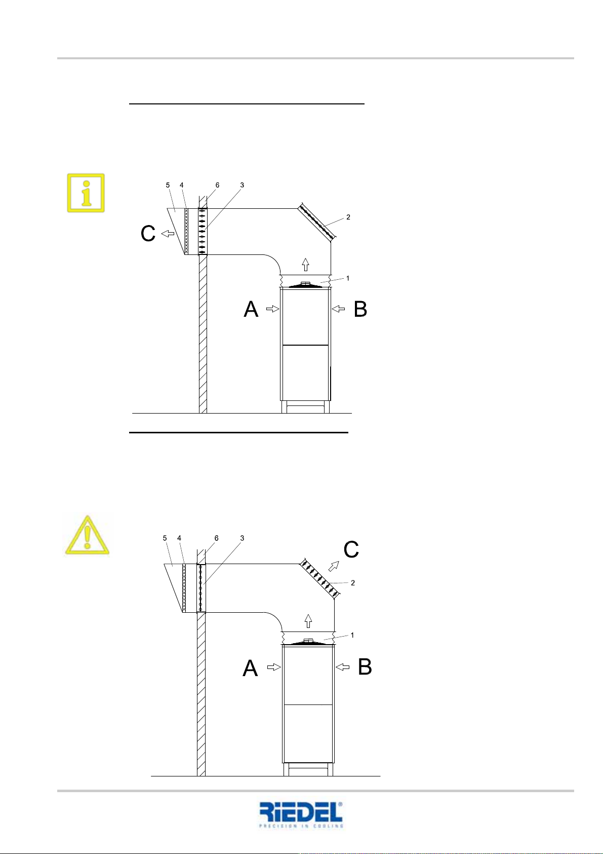
Summer operation – exhaust air directed outside
For summer operation, the multi-leaf damper (2) must be closed and multi-leaf damper (3) opened.
This ensures that the waste heat from the cooling unit is directed outside.
A sufficient air supply to the intake area of the cooling unit must be ensured.
Winter operation – exhaust air directed inside
For winter operation, the multi-leaf damper (3) must be closed and multi-leaf damper (2) opened.
This ensures that the waste heat from the cooling unit is directed inside to be used for heating
purposes.
If the multi-leaf damper (3) is not closed or not sealed and the outside air temperature
is < 0°C, the cooling unit may freeze, thus resulting in a total loss.
A Air inlet
B Air inlet
C Air outlet
1. Flexible connecting element
2. Multi-leaf damper, inside
3. Multi-leaf damper, outside
4. Bird screen
5. Firedamp protection
6. External building wall
Example figure
1. Flexible connecting element
2. Multi-leaf damper, inside
3. Multi-leaf damper, outside
4. Bird screen
5. Firedamp protection
6. External building wall
A Air inlet
B Air inlet
C Air outlet
Example figure