'操作说明 Hotflow THREE_26_zh.pdf - 第547页
15. OPTIONS AND ACCESSORIES ENGLISH Translation of the original 90 451820.66.03_EN 2020-05-05 15.6 Outdoor installation The cooling unit must be equipped with this option in the case of outdoor installation. Since they w…
Translation of the original ENGLISH 15. OPTIONS AND ACCESSORIES
451820.66.03_EN
2020-05-05
89
15.5.2 Operating modes
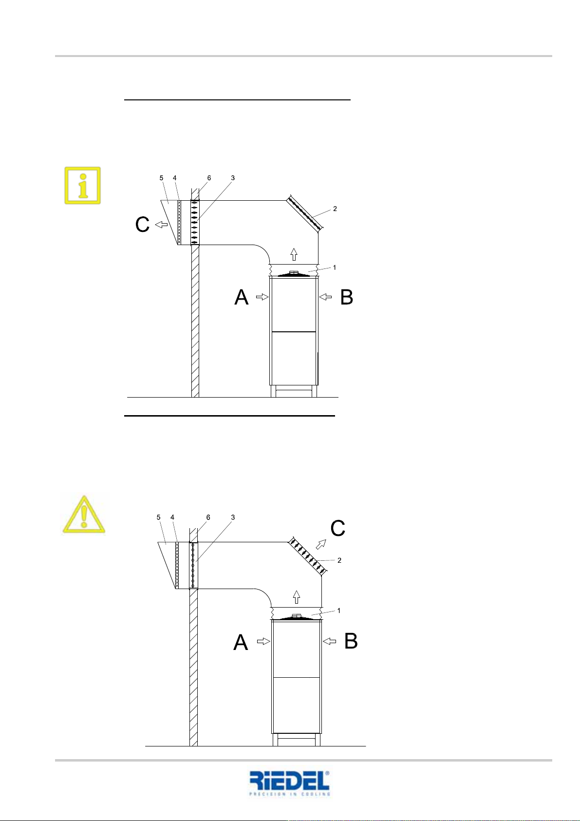
Summer operation – exhaust air directed outside
For summer operation, the multi-leaf damper (2) must be closed and multi-leaf damper (3) opened.
This ensures that the waste heat from the cooling unit is directed outside.
A sufficient air supply to the intake area of the cooling unit must be ensured.
Winter operation – exhaust air directed inside
For winter operation, the multi-leaf damper (3) must be closed and multi-leaf damper (2) opened.
This ensures that the waste heat from the cooling unit is directed inside to be used for heating
purposes.
If the multi-leaf damper (3) is not closed or not sealed and the outside air temperature
is < 0°C, the cooling unit may freeze, thus resulting in a total loss.
A Air inlet
B Air inlet
C Air outlet
1. Flexible connecting element
2. Multi-leaf damper, inside
3. Multi-leaf damper, outside
4. Bird screen
5. Firedamp protection
6. External building wall
Example figure
1. Flexible connecting element
2. Multi-leaf damper, inside
3. Multi-leaf damper, outside
4. Bird screen
5. Firedamp protection
6. External building wall
A Air inlet
B Air inlet
C Air outlet
Example figure
15. OPTIONS AND ACCESSORIES ENGLISH Translation of the original
90
451820.66.03_EN
2020-05-05
15.6 Outdoor installation
The cooling unit must be equipped with this option in the case of outdoor installation.
Since they will be operated in the cold outside air, only cooling units with a start-up help for winter
are generally suitable for this option, provided they are operated with a glycol-water mixture with a
concentration of at least 35%.
Failure to adhere to this poses a risk of freezing (ambient temperature </= +5°C) for the
cooling unit with subsequent total loss.
To ensure error-free operation of the cooling unit and to permit necessary maintenance and repair
work, the minimum clearances and free spaces must be observed during installation. The air must
be free of dust and aggressive gases.
See technical section (dimension sheet)
These installation conditions must be observed to guarantee that the cooling air can be sucked in
and blown out freely. This largely prevents the heated air blown out at the top from being sucked in
(air short circuit). In the area of the cooling unit, sufficient air exchange must be ensured to enable
effective heat dissipation.
When installing the cooling unit outdoors, the relevant local regulations must be observed, e.g.:
• Water protection directives (see chapter 10 "Environmental requirements")
• Noise emission directives
Electrotechnical connection:
• Provide the cooling unit with a separate supply.
• Supplying the cooling unit from an external control cabinet is not permitted.
Due to the risk of frost when the system is at a standstill, the cooling unit is equipped with the
following components to keep the system at operating temperature:
• Cooling unit with its own mains isolation switch
• Electric heating elements in the stainless steel tank of the cooling unit
• Thermostatic pump start-up control
• Monitoring of the water temperature where there is a danger of frost
• Band heating system for compressors
• Additional corrosion protection measures against the effects of the weather
• Water circuits primarily with ABS pipes
• Float switch
Translation of the original ENGLISH 15. OPTIONS AND ACCESSORIES
451820.66.03_EN
2020-05-05
91
Function:
Following switch-off of the consumer in the frost period, the mains isolation switch for the cooling
unit must remain switched on, thus enabling the pumps and the electric heating to enter standby
mode.
If the temperature in one of the water circuits sinks, the pump(s) and the electric heating are
switched on. The pumps and the electric heating are switched off again when the frost protection
setpoint temperature is reached.
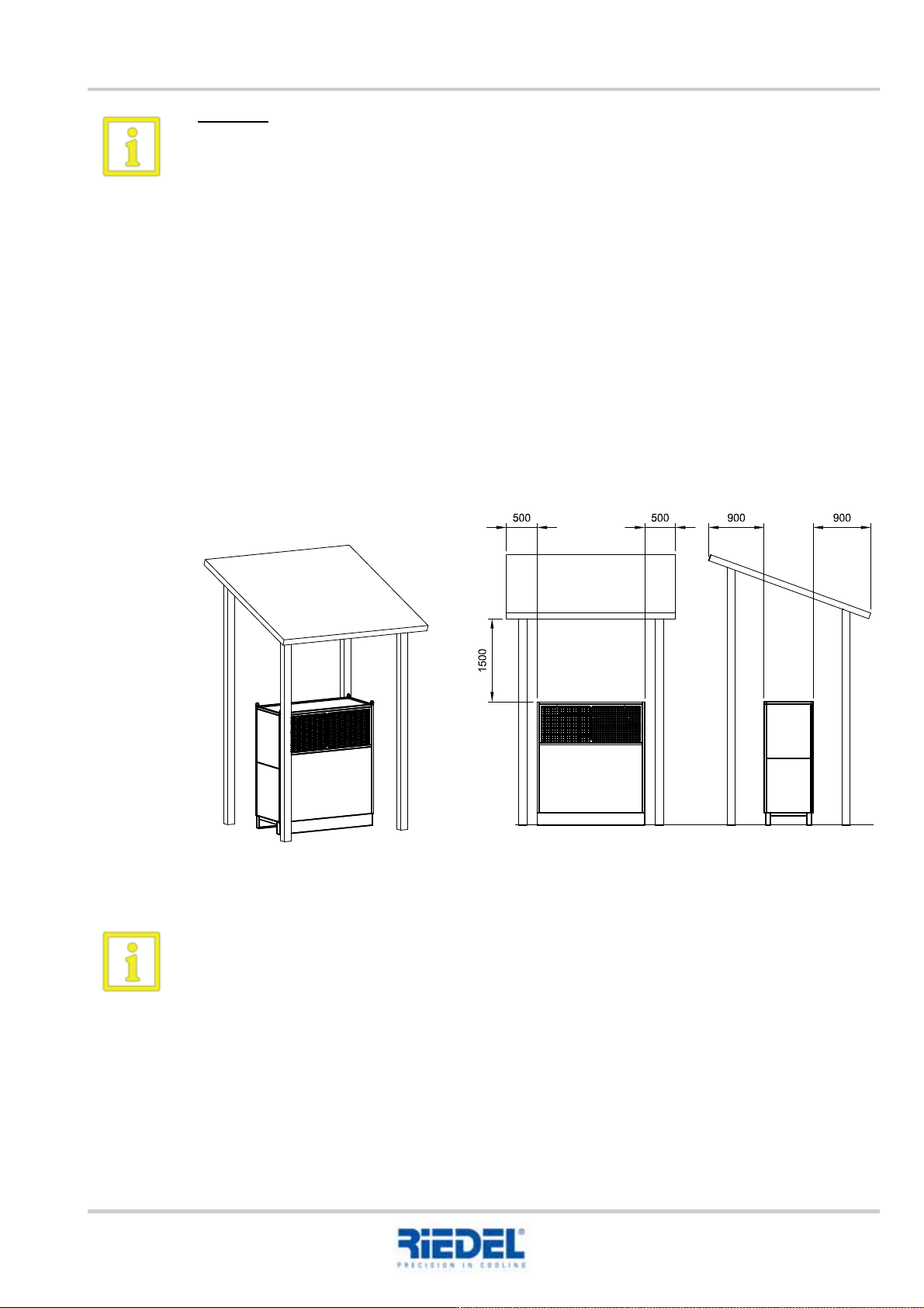
The minimum clearances must be complied with during installation to ensure error-free operation of
the cooling unit and sufficient space for maintenance and repair work, in accordance with the
diagram.
• Use a weather protection cover
This reduces the risk of the liquefier or fans becoming blocked with snow, leaves, dust etc.
Moreover, the cooling unit is not exposed to direct sunlight. We recommend the use of heat-
reflecting material at the installation location.
Example figure
The wind load and, if applicable, the snow load must generally be taken into consideration if
the cooling unit is installed outdoors, and especially if it is installed in an exposed position,
for example, on the roof of a building. The cooling unit may need to be firmly fixed to the sub-
surface.