YS12P_YS12F_Mainte_E.pdf - 第101页
3-36 3 Periodic maintenance items 5.2 Cleaning the scan camera (YS12P) T he light diffuser plate and prism of the scan camera may become dirty . P eriodic cleaning is recommended. c CAUTION Do not apply strong for ce to …
3-35
3
Periodic maintenance items
5. Six-month inspection
5.1 Cleaning the fiducial camera
The fiducial mark recognition camera is mounted on the right (or left as an option) of the head unit.
The camera unit may become dirty with dust due to the long-term use of the machine. Periodic cleaning is
recommended.
c
CAUTION
Do not apply strong force or shock to the camera unit and lighting unit during cleaning. Optical axis adjustment might
become unreliable.
c
CAUTION
If trouble occurs with the lighting unit, then contact YAMAHA sales representative. Disassembly and cleaning of the
lighting unit by the user will void the warranty.
e
1
Move the head unit.
1. Press the emergency stop button to open
the machine safety cover.
2. Move the head unit forward.
2
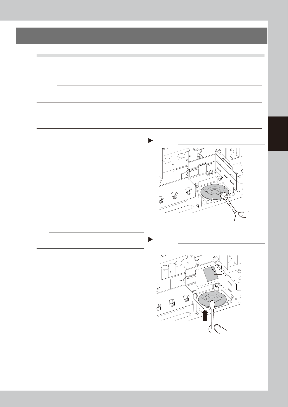
Clan the lighting unit.
Use a blower brush to remove the dust from
the lighting unit.
53365-L6-00
3
Clean the reflector plate.
Use a cotton swab slightly dampened with
lens cleaner to clean the reflector plate side
shown in the figure on the right.
53366-L6-00
TIP
The blower brush and lens cleaner are optional
purchase items.
Step 2
Using a blower brush to remove dust
Fiducial camera lighting unit Blower brush
Step 3
Cotton swab dampened
with lens cleaner
Cleaning the reflector plate
Reflector plate
3-36
3
Periodic maintenance items
5.2 Cleaning the scan camera (YS12P)
The light diffuser plate and prism of the scan camera may become dirty. Periodic cleaning is recommended.
c
CAUTION
Do not apply strong force to the camera parts during cleaning. Doing so may damage the glass components used in
the camera unit.
1
Remove the nozzles from all heads.
If nozzle station is equipped with the machine:
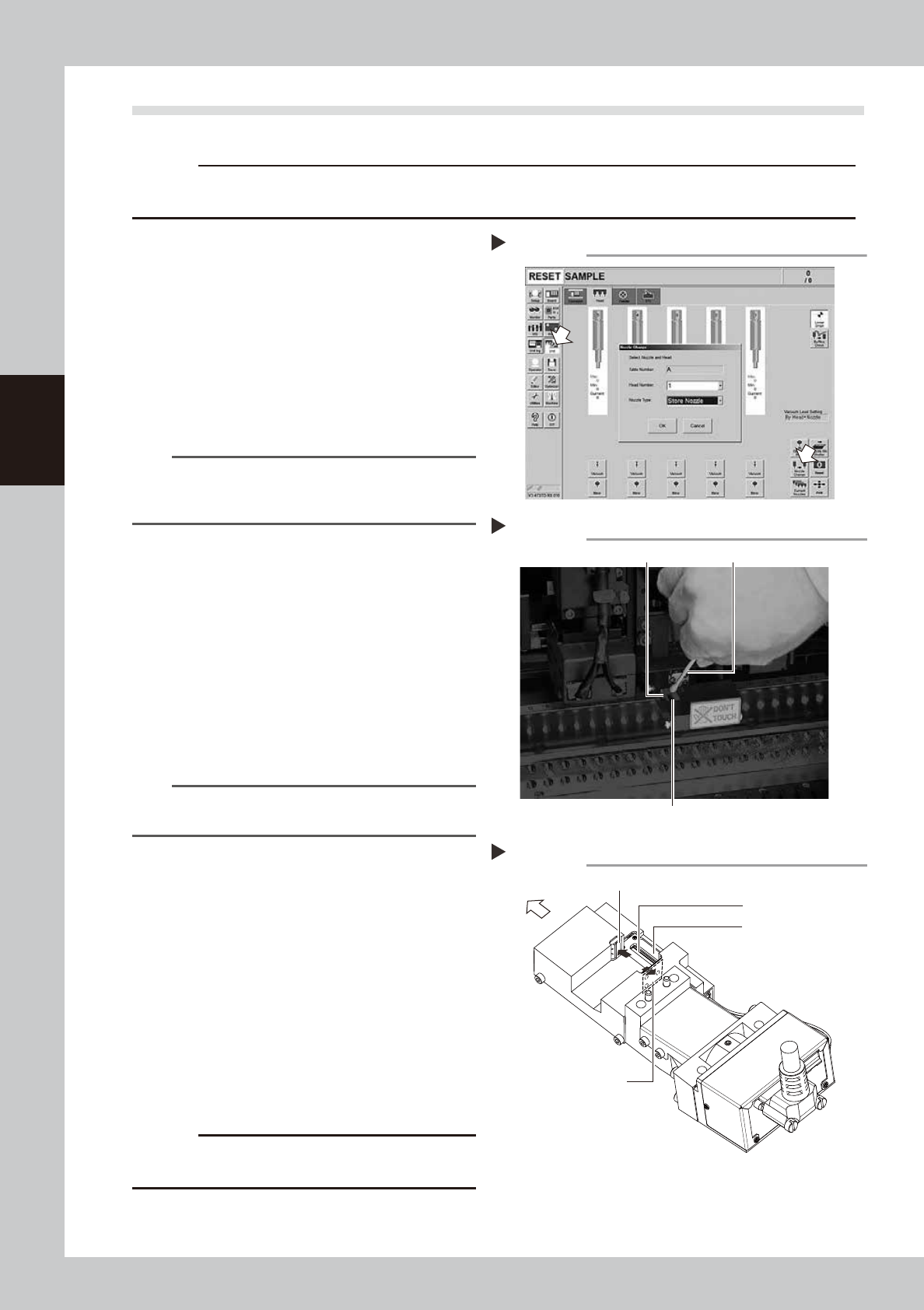
1. Press the [Nozzle Change] button on the
[Unit] - [Head] screen.
2. Select "ALL" for the Head Number and
select "Store Nozzle" for Nozzle type on
the "Nozzle Change" screen.
3. Press the [OK] button. The nozzles of all
heads are stored to the nozzle station.
54312-L6-10
n
NOTE
If the machine is not equipped with the nozzle station,
press the emergency stop button and then open the
machine safety cover to remove nozzles manually.
e
2
Move the head unit forward.
1. Press the emergency stop button to open
the machine safety cover.
2. Move the head unit forward.
3
Move the scan camera.
1. Move all heads (nozzle holder sections)
manually to their upper ends.
2. Move the scan camera to the right side of
the R-axis motor. At this point, do not
apply excessive force to the scan camera.
n
NOTE
When the machine has only one fiducial camera, moving
the scan camera to the left end will make cleaning easier
.
4
Wipe the diffuser plate and prism.
1. Use a cotton swab to remove dust and
dirt on the upper surface of the main
light diffuser plate and on the prism
surface. As the prism surface is narrow,
twist the end of the cotton swab into a
pointed tip and use it to wipe the prism
surface lightly.
2. Wipe the side-view light diffuser plate and
prism using a cotton swab. Use a hand
mirror when wiping the prism surface as it
cannot be seen from the front.
53360-L6-00
53361-L6-00
c
CAUTION
Do not use solvent. It may cause the surface finish of the
prism to peel or flake and the diffuser plate to discolor.
5
Return the nozzles.
Return the nozzle to its original head if nozzle
was removed manually.
Returning all nozzles to nozzle station.
Step 1
Cleaning the light diffuser plate and prism
Step 4
Light diffuser plate
Prism
Cotton swab
Cleaning points of light diffuser plate and prism
Main diffuser plate
Side-view diffuser plate
Side-view prism
Front of machine
Main prism
Step 4
3-37
3
Periodic maintenance items
5.3 Cleaning and lubricating the W-axis
The following describes the cleaning and lubrication procedures for the W-axis. For details about lubrication
points and styles, see "Chapter 5 Lubrication points and schedule".
1
Change the conveyor width to its
maximum width.
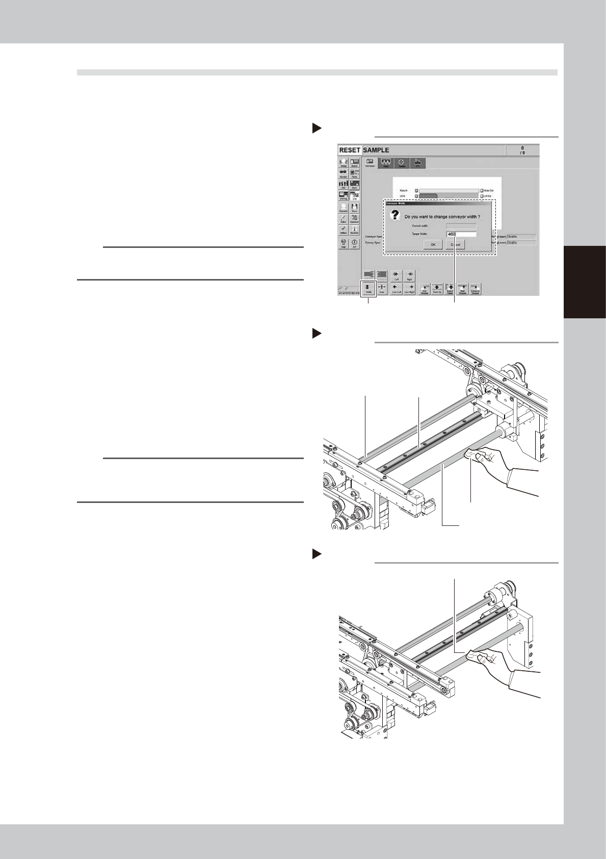
1. Press the [Width] button to display the
"Conveyor Width" screen.
2. Enter the maximum value of the conveyor
width in the "Target Width" box and press
the [OK] button. The conveyor width is
changed to the specified width.
543171-L6-10
TIP
The maximum conveyor width is 460 mm or 410 mm as
a standard feature.
e
2
Clean the each part of W-axis.
1. Press the emergency stop button and
then open the machine safety cover.
2. If the machine is equipped with a
carriage, remove the carriage to easily
access to the W-axis.
3. Wipe the old grease and soiling from the
W axis ball screw, guide, and the whole
hexagon spline with a lint-free cloth that
does not raise dust.
53367-L6-00
n
NOTE
Carefully wipe the lead grooves of the ball screw during
the cleaning work. Additionally, make sure that any dirt
is not produced.
3
Change the conveyor width to its
minimum width.
1. Close the machine' safety cover, and
cancel the emergency stop. In case the
specification has a carrier, set the carrier.
2. Press the [Width] button to display the
"Conveyor Width" screen.
3. Enter the minimum value of the conveyor
width "50 mm" in the "Target Width" box
and press the [OK] button. The conveyor
width is changed to the specified width.
e
4
Clean the rest of the part.
1. Press the emergency stop button and
then open the machine safety cover.
2. If the machine is equipped with a
carriage, remove the carriage to easily
access to the W-axis.
3. Wipe off the remaining grease or soiling
describes in Step 2 with a lint-free cloth.
53368-L6-00
Step 1
Changing the conveyor width
[Width] button Enter the maximum conveyor width.
Step 2
Cleaning the W-axis
Ball screw
Cleaning cloth
Hexagon spline
Guide
Step 4
Cleaning the W-axis 2
Wipe off remaining grease or soiling.