YS12P_YS12F_Mainte_E.pdf - 第105页
3-40 3 Periodic maintenance items 6.2 Cleaning and replacing the blow station filter (option) T his section describes how to clean and replace the filter used in the machines equipped with a blow station (option). c CAUT…
3-39
3
Periodic maintenance items
6. One-year inspection
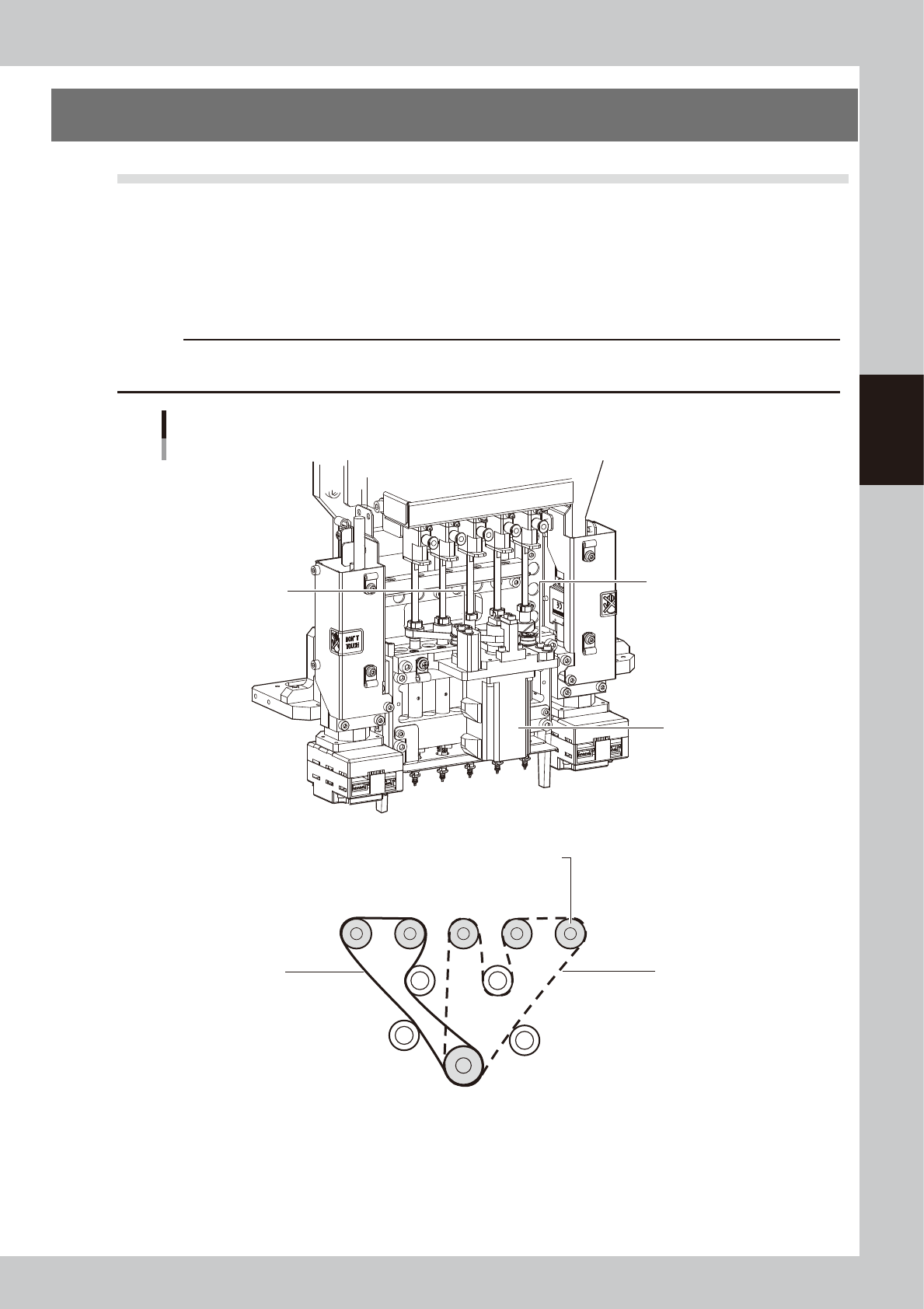
6.1 Checking the R-axis spline belt condition
There are 2 R-axis spline belts. Check the condition of each belt.
n
R-axis spline belt checkpoints
• Is the belt becoming frayed due to cracks and belt wear?
• Is the belt splitting due to cracks or deterioration?
• Is the belt tension too loose? Is the belt itself loose?
c
CAUTION
If trouble occurs with an R-axis spline belt, contact YAMAHA sales representative. Disassembly and cleaning of the
spline belt by the user will void the warranty.
Spline for Head 1
Spline belt
R-axis belt (upper belt)
R-axis belt (lower belt)
Belt tensioner
Belt tensioner
Belt tensioner
Belt tensioner
R-axis motor
53345-L6-00
3-40
3
Periodic maintenance items
6.2 Cleaning and replacing the blow station filter (option)
This section describes how to clean and replace the filter used in the machines equipped with a blow station
(option).
c
CAUTION
If trouble occurs with the blow station, contact YAMAHA sales representative. Disassembly and cleaning of the blow
station by the user will void the warranty.
1
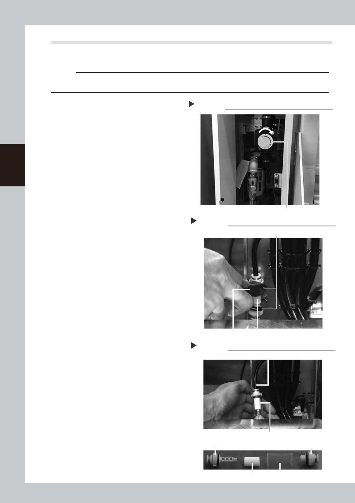
Turn the machine’s air supply OFF.
Turn the air supply/exhaust switch inside the
panel at lower left of the machine clockwise
to turn the air supply OFF.
53346-L6-10
e
2
Cut the cable ties on the filter.
1. Press the emergency stop button, and
open the machine’s safety cover. In case
the specification has a carrier, remove
the carrier.
2. Using a wire cutter or similar tool, cut the
cable ties that hold the filter unit inside
the blow station stand.
53347-L6-00
3
Disconnect the air hose from one
end of the filter unit and remove
the filter.
1. Disconnect the air hose from one end of
the in-line filter unit.
2. Remove the filter joint caps on both sides
of the filter by rotating them 90 degrees.
3. Pull the transparent case to remove it
and take out the filter.
53348-L6-00
4
Clean the filter.
Use an air blow tool to blow air through the
filter from the inside and from the outside. If
the filter is excessively dirty and cannot be
cleaned, replace it with a new filter.
• Inline filter (unit)
KGR-M9934-01X INLINE FILTER
• Filter
KGR-M9934-FOX FILTER, SPARE
5
Return the filter
Place the filter with new cable ties.
Cutting the cable tie
Step 2
Cable tie
Wire cutter In-line filter unit
Taking out the filter
Step 3
Air hose
Filter
Transparent filter case
In-line filter unit
Filter joint caps
Step 1
Turning off air supply
Air supply/exhaust switch
3-41
3
Periodic maintenance items
6.3 Checking the nozzle station sensor condition (option)
When the machine is equipped with a nozzle station (option), check the nozzle station sensors condition.
c
CAUTION
If a nozzle station sensor fails to detect a nozzle, the nozzle change cannot be performed correctly and the machine
operation may be interrupted due to a nozzle detection error.
e
1
Press the emergency stop button.
The machine should be in emergency stop
to ensure safety during work.
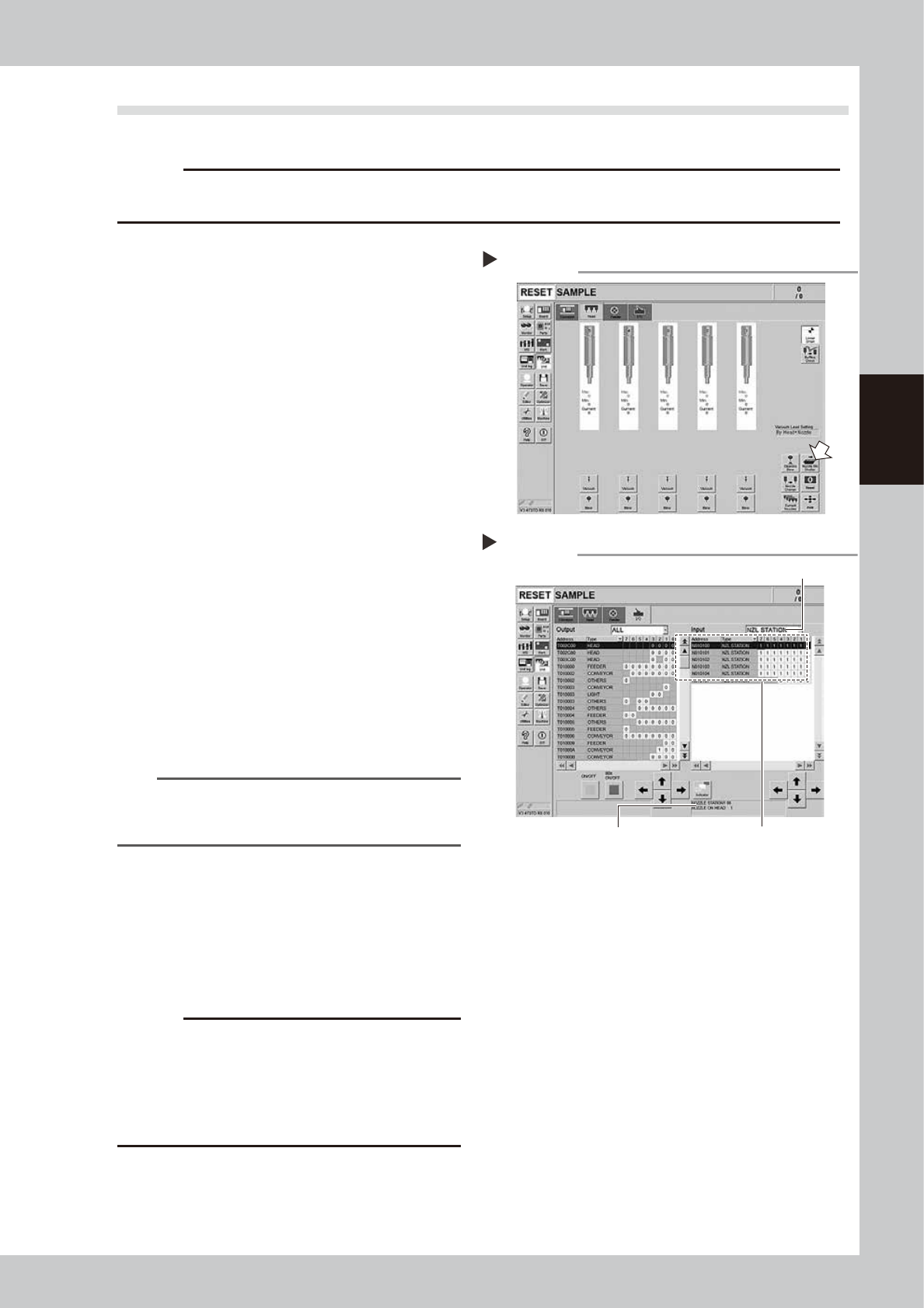
2
Open the nozzle station shutter.
1. Open the [Unit] - [Head] screen.
2. Press the [Nozzle Stn Shutter] button to
open the nozzle station shutter.
54303-L6-10
3
Check the detection status of the
nozzle station sensors.
Check to see if the nozzle station sensors
detect the presence or absence of nozzles.
1. Open the [Unit] - [I/O] screen.
2. From the "Input" drop-down list, select
"NZL STATION".
3. While detaching/attaching a nozzle
from/to the nozzle station, check if the
sensor detects the nozzle correctly.
The detection status on the screen should
read "1" when the nozzle is detached
from the nozzle station, and should read
"0" when the nozzle is attached to the
nozzle station.
54306-L6-10
TIP
The nozzle station position No. where a nozzle was
detached or attached is displayed on the lower part of
the "Input" status screen.
4
Clean the nozzle station.
If the nozzle detection status is different from
the actual nozzle presence status, remove
the nozzle and visually check the nozzle
setting position. If any dust or chip is found,
remove it and clean the inside of the nozzle
with the vacuum assembly.
c
CAUTION
If the nozzle detection status inside the nozzle station
does not become stable for a reason other than clear
reason, such as dust, etc., or if the nozzle cannot be
detected, contact YAMAHA sales representative.
Disassembly and cleaning of the nozzle station sensors
by the user will void the warranty.
5
Close the nozzle station shutter.
On the [Unit] - [Head] screen, press the
[Nozzle Stn Shutter] button to close the
nozzle station shutter.
Opening the shutter
Step 2
Checking the nozzle detection status
Step 3
Select "NZL STATION".
Nozzle station position No. is
displayed here.
Shows the presence or absence
of nozzles detected by sensors.