PSV5000_OwnersManual.pdf - 第110页
Maint enance ■ Pick and Place Prob e - 106 - Data I/O ■ 096 - 0 465 - 00 1C completing the Z - Axis adjustment does not reduce or e lim inate s ubse quent pick errors, complete the vacuum sensor adjustments described her…
Pick and Place Probe Adjusting the Vacuum Generator Sensor
PSV5000 Owner’s Manual - 105 -
workspace.
When working within the machine workspace, moving the PNP head must
be the responsibility of only one qualified individual. All others must stay
clear of the machine controls to prevent injury to that person.
Ensure that a job is Paused or Finished, or the system power is OFF prior to
opening any safety doors.
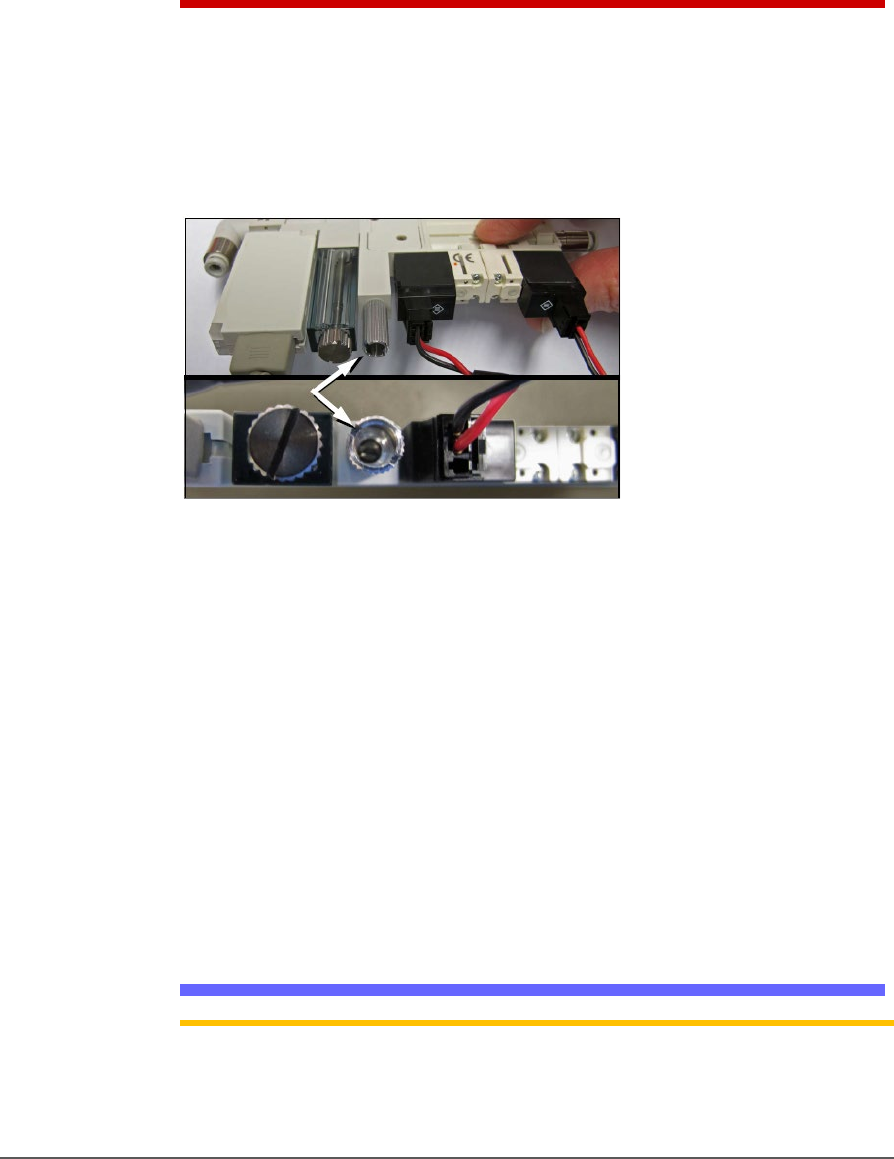
5. Locate the actual vacuum generator (Data I/O PN 815-0047-001) on
the right side of the PNP head. Find the blow-off adjustment
set-screw. It is inside a long knurled stem which needs to be
loosened before adjusting the set-screw. See the figure below.
Figure 61: The Blow-off adjustment set-screw on the vacuum
generator is inside a knurled locking stem (arrow). (The vacuum
block must NOT be removed as shown here.)
6. Turn the adjustment screw until the vacuum generator readout
displays +1.5 to 2.0 kPa.
7. While holding the set screw with the screwdriver, tighten the knurled
stem.
8. Do the same for the other probe.
9. Click Blow-off to the OFF position.
If you had a blow-off problem, test your results.
Adjusting the Vacuum Generator Sensor
Note: If you notice consecutive programming pick errors, before adjusting
vacuum sensors complete the Z-Axis adjustment. For instructions on Z-Axis
adjustment, see Teaching the Workspace Locations on page
69. If
Maintenance ■ Pick and Place Probe
- 106 - Data I/O ■ 096-0465-001C
completing the Z-Axis adjustment does not reduce or eliminate subsequent
pick errors, complete the vacuum sensor adjustments described here.
Vacuum sensors on the PSV5000 System are adjustable. The I/O
Interface window displays a list of the sensors in the PSV5000 System
and the status of each sensor.
Note: The number of sensors on the PSV5000 System depends on the
options installed.
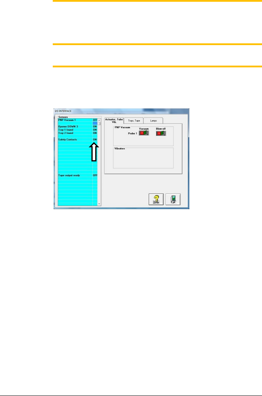
To view the status of sensors at the main CH700 Setup window, click
System > Misc. I/O.
Figure 62: The I/O Interface window reports sensor status and
allows switching options on or off.
TO ADJUST PROBE VACUUM GENERATOR SENSORS:
1. Finish a job.
2. At the Gantry window, move the PNP head to the Park position.
3. Close the Gantry window and at the System window click Misc. I/O.
4. At the I/O Interface tab, click the Vacuum toggle ON and the
Blow-off toggle OFF. Refer to the figure above.
5. Open the rear safety door.
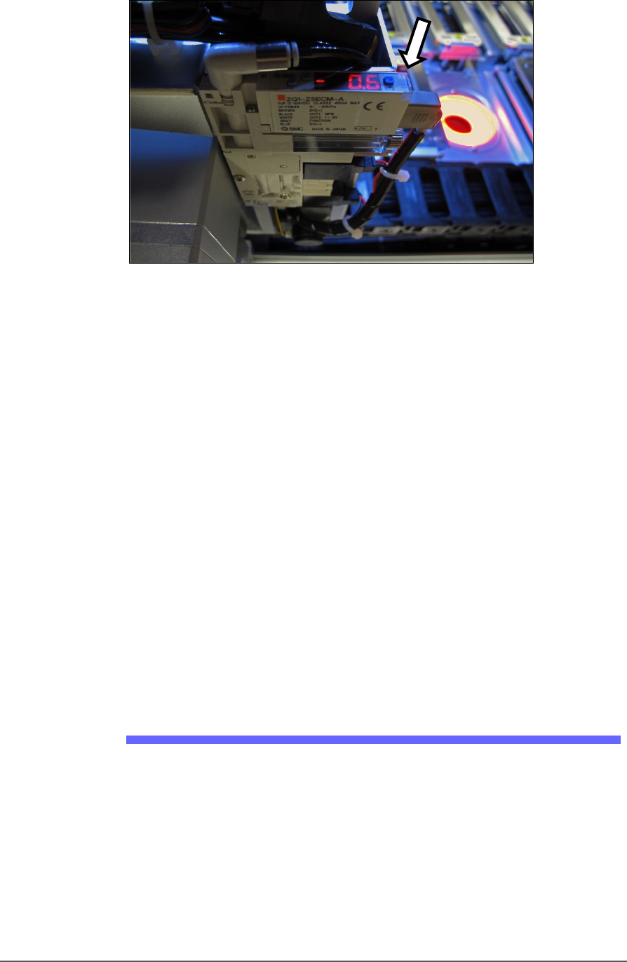
6. With a device or clean finger, plug probe tip 1 and ensure the green
generator lamp comes on. See the figure below.
Pick and Place Probe Replacing the Input Air Filter
PSV5000 Owner’s Manual - 107 -
Figure 63: The PNP Probe vacuum generator adjustments. (Looking
in from the back of the machine) the vacuum generator faces up.
The green lamp (arrow) is currently off.
7. Read the high and low values each time you plug the air with your
finger and release it. They are needed for the next step.
8. Set the trigger value on the sensor by pressing the S (blue SET)
button on the vacuum generator block and then using the UP or
DOWN buttons, set the value to midway between the high value and
the low value. It should be approximately -40 kPa.
9. Press the SET button again.
10. Check adjustment by blocking and unblocking the probe tip several
times and ensuring the green lamp goes on and off each time.
11. Repeat these steps for probe 2.
12. Turn OFF the vacuum switch for the probe.
Wipe the probe tip with a clean dry cloth.
Replacing the Input Air Filter
1. If a job is running, Pause or Finish the job.
2. Turn off shop air and disconnect the input air line from the Air
Filter/Regulator at the quick connect fitting.
3. Unscrew the air contamination collection bowl housing.
4. Pull off the clear collection bowl. Clean out any dirt, oil, or water.
5. Unscrew the black knob below the filter.
6. Pull off the filter. Clean or replace as necessary.