PSV5000_OwnersManual.pdf - 第111页
Pick and Place Prob e Replacing the Input Air Filter PSV5000 O wner ’s M anual - 107 - Figure 63: The PNP Pro be v acuu m genera t or adju s tments. (Looking in f rom th e back of th e machi ne) the vac uum ge ner at…
Maintenance ■ Pick and Place Probe
- 106 - Data I/O ■ 096-0465-001C
completing the Z-Axis adjustment does not reduce or eliminate subsequent
pick errors, complete the vacuum sensor adjustments described here.
Vacuum sensors on the PSV5000 System are adjustable. The I/O
Interface window displays a list of the sensors in the PSV5000 System
and the status of each sensor.
Note: The number of sensors on the PSV5000 System depends on the
options installed.
To view the status of sensors at the main CH700 Setup window, click
System > Misc. I/O.
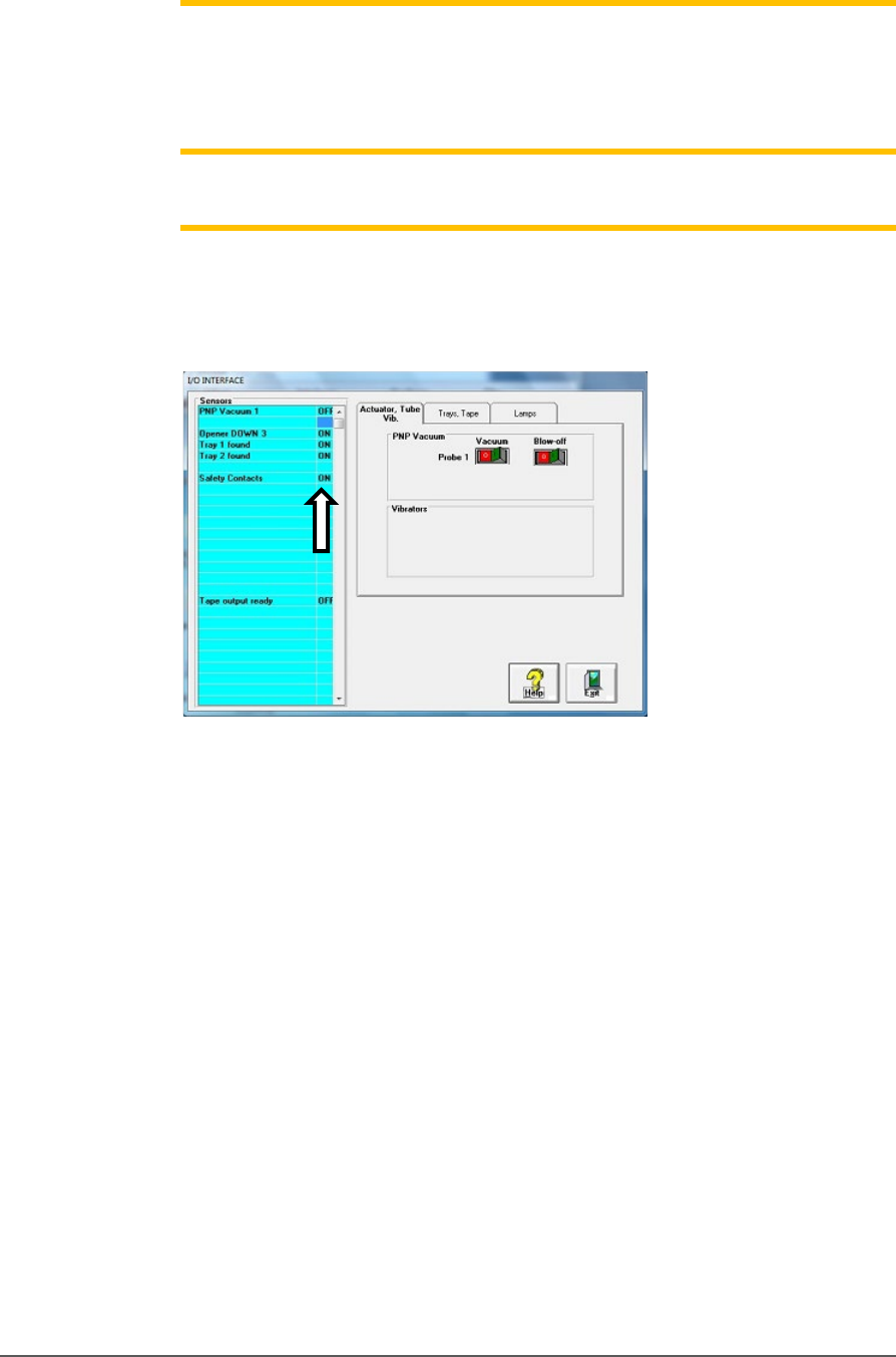
Figure 62: The I/O Interface window reports sensor status and
allows switching options on or off.
TO ADJUST PROBE VACUUM GENERATOR SENSORS:
1. Finish a job.
2. At the Gantry window, move the PNP head to the Park position.
3. Close the Gantry window and at the System window click Misc. I/O.
4. At the I/O Interface tab, click the Vacuum toggle ON and the
Blow-off toggle OFF. Refer to the figure above.
5. Open the rear safety door.
6. With a device or clean finger, plug probe tip 1 and ensure the green
generator lamp comes on. See the figure below.
Pick and Place Probe Replacing the Input Air Filter
PSV5000 Owner’s Manual - 107 -
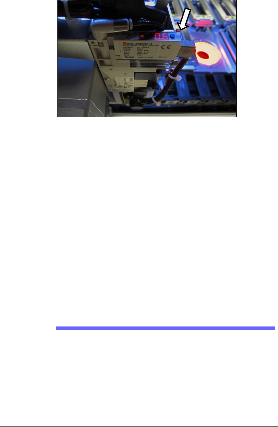
Figure 63: The PNP Probe vacuum generator adjustments. (Looking
in from the back of the machine) the vacuum generator faces up.
The green lamp (arrow) is currently off.
7. Read the high and low values each time you plug the air with your
finger and release it. They are needed for the next step.
8. Set the trigger value on the sensor by pressing the S (blue SET)
button on the vacuum generator block and then using the UP or
DOWN buttons, set the value to midway between the high value and
the low value. It should be approximately -40 kPa.
9. Press the SET button again.
10. Check adjustment by blocking and unblocking the probe tip several
times and ensuring the green lamp goes on and off each time.
11. Repeat these steps for probe 2.
12. Turn OFF the vacuum switch for the probe.
Wipe the probe tip with a clean dry cloth.
Replacing the Input Air Filter
1. If a job is running, Pause or Finish the job.
2. Turn off shop air and disconnect the input air line from the Air
Filter/Regulator at the quick connect fitting.
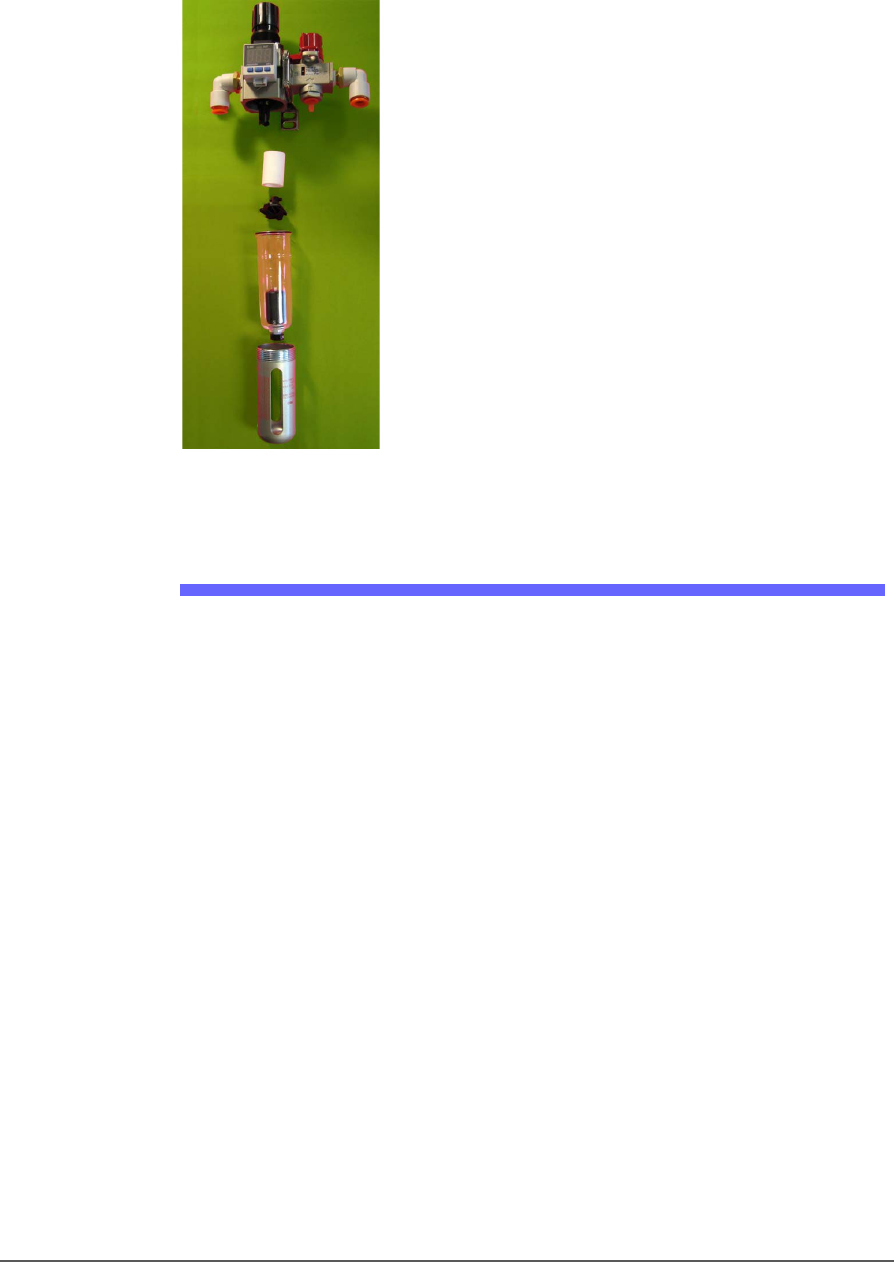
3. Unscrew the air contamination collection bowl housing.
4. Pull off the clear collection bowl. Clean out any dirt, oil, or water.
5. Unscrew the black knob below the filter.
6. Pull off the filter. Clean or replace as necessary.
Maintenance ■ Pick and Place Probe
- 108 - Data I/O ■ 096-0465-001C
Reinstall in reverse order being careful not to damage the O-Ring on the
bowl.
Reconnect the shop air supply line.
Figure 64: Replacing the Air Filter/Regulator.
Vacuum Generator Filters and Silencers
These procedures cover removing and cleaning or replacing vacuum
generator parts for vacuum generators on PSV5000 head.
A clogged or dirty vacuum filter or silencer can cause dropped devices
and placement problems at the PNP head.
REQUIREMENTS
• metric hex key set
• flat screwdriver
• small Phillips screwdriver
VACUUM GENERATOR FI LT E R S
1. Finish a job if one is running.
2. Use the Gantry window to move the PNP head to an accessible
location such as the Tool position.
3. Properly shut OFF the PSV5000 System. See Shutting Down the
PSV5000 System on page 38.