PSV5000_OwnersManual.pdf - 第116页
Maint enance ■ Pick and Place Prob e - 112 - Data I/O ■ 096 - 046 5 - 00 1C Figure 67: Two of the four grease ducts on the r ear linea r guide of the gant ry . Note: Too much grease may cause grease to splatter inside th…
Pick and Place Probe Inspecting Gantry Parts
PSV5000 Owner’s Manual - 111 -
REQUIREMENTS
• AFB‐LF from THK Grease
• hex key set (Allen wrenches)
WARNING: Possible collision hazard! The high speed and force of
the gantry can seriously harm anyone working inside the
workspace.
When working within the machine workspace, moving the PNP head must
be the responsibility of only one qualified individual. All others must stay
clear of the machine controls to prevent injury to that person. Ensure that
the system power is OFF prior to proceeding.
WARNING: Possibility of serious eye damage! AFB LF grease
causes serious eye irritation. Wear eye protection goggles.
GANTRY X-AXIS LUBRICATION
1. Move the PNP head to the Park position.
2. Properly shut OFF the PSV5000 sub-systems and machine power.
See Shutting Down the PSV5000 System on page 38.
3. The guard on the back linear guide must slide out to the left or right.
Therefore, remove either the left or right clear workspace side panel.
Remove the four screws (4 mm hex key) and lift the panel off.
4. Open the rear safety doors and remove the four screws in the gantry
guard with a 2.5 mm hex key.
5. At the open side of the machine, lift the end of the guard slightly and
pull it out of the workspace.
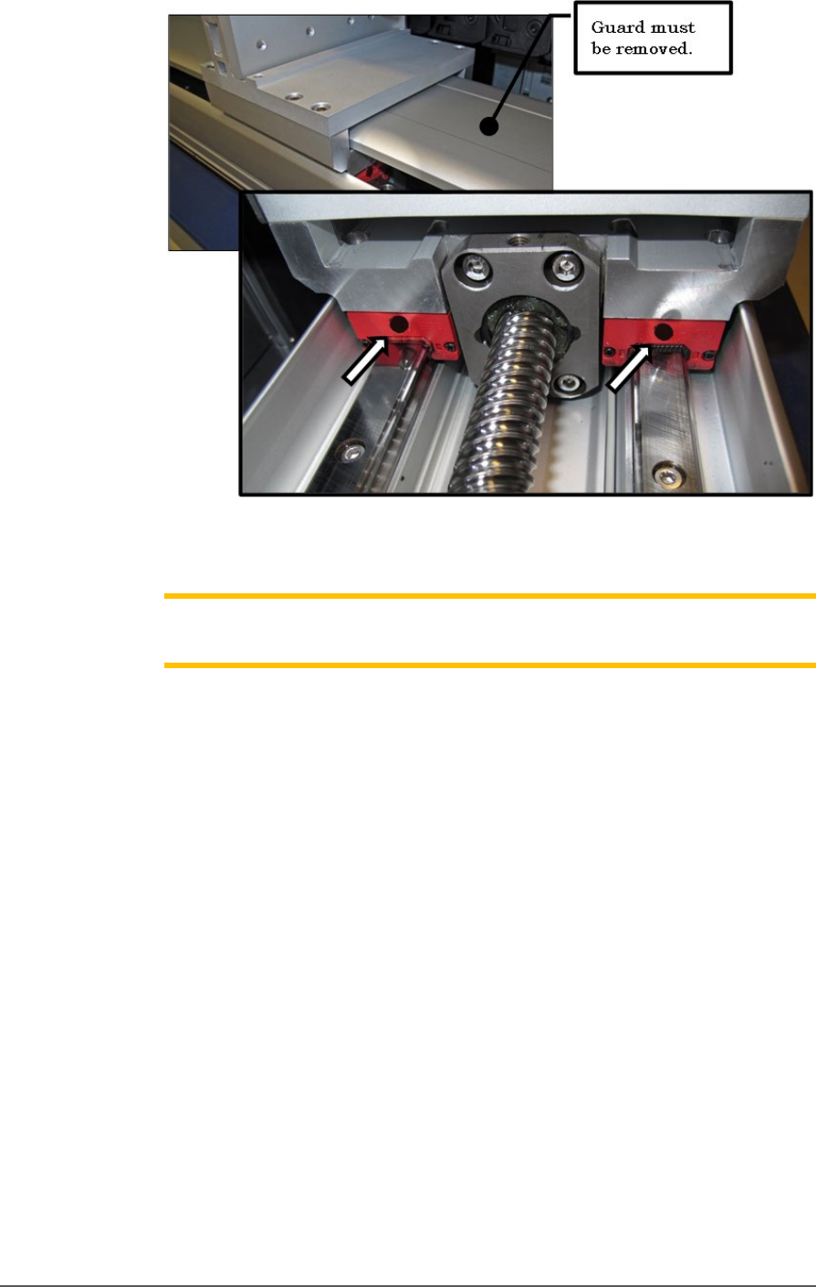
6. Remove the two screws covering the grease ducts.
7. Apply grease to the two grease ducts on each end of the slide block
(as shown on the next page). Wipe off any excess.
8. Replace/insert the screws removed from Step 6.
Maintenance ■ Pick and Place Probe
- 112 - Data I/O ■ 096-0465-001C
Figure 67: Two of the four grease ducts on the rear linear guide of
the gantry.
Note: Too much grease may cause grease to splatter inside the work
envelope. Do not over-apply the grease.
9. Lubricate the rear ball screw after wiping off the old grease. Directly
apply new grease to the ball screw sparingly. Wipe off any excess.
10. Open the front safety doors and remove the four screws securing the
front guard of the front linear guide of the gantry (2 mm hex key).
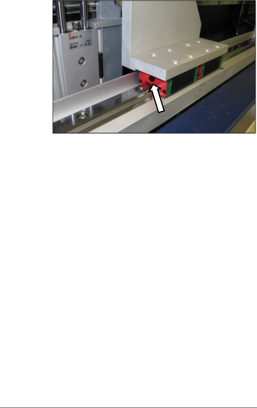
11. Remove the screw covering the grease duct.
12. Apply grease to the grease duct on each end of the slide block. Wipe
off any excess. See figure below.
Pick and Place Probe Inspecting Gantry Parts
PSV5000 Owner’s Manual - 113 -
Figure 68: One of the two front gantry rail lube ducts. Note that the
guard has already been removed.
10. Lubricate the front ball screw after wiping off the old grease. Directly
apply new grease to the ball screw sparingly. Wipe off any excess.
11. Replace all screws, guards, and shields.
GANTRY Y-AXIS LUBRICATION
1. Open the front and rear safety doors and remove the four screws
securing the guard of the Y-axis linear guide (2 mm hex key).
2. Slide the guard out from either the front or back after pulling slightly
to clear the end cap.