PSV5000_OwnersManual.pdf - 第118页
Maint enance ■ Pick and Place Prob e - 114 - Data I/O ■ 096 - 0 465 - 00 1C A spare Prob e Assem bly comes with the Self - Service S pares Kit. Figure 69: The Y - axis g antry bal l scre w and gui de block , with cover (…
Pick and Place Probe Inspecting Gantry Parts
PSV5000 Owner’s Manual - 113 -
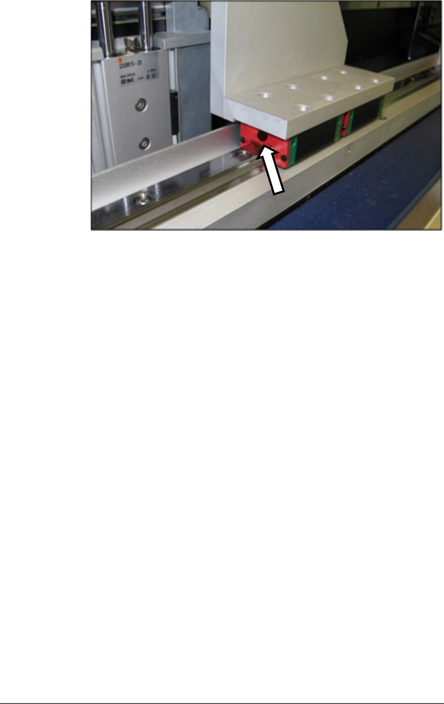
Figure 68: One of the two front gantry rail lube ducts. Note that the
guard has already been removed.
10. Lubricate the front ball screw after wiping off the old grease. Directly
apply new grease to the ball screw sparingly. Wipe off any excess.
11. Replace all screws, guards, and shields.
GANTRY Y-AXIS LUBRICATION
1. Open the front and rear safety doors and remove the four screws
securing the guard of the Y-axis linear guide (2 mm hex key).
2. Slide the guard out from either the front or back after pulling slightly
to clear the end cap.
Maintenance ■ Pick and Place Probe
- 114 - Data I/O ■ 096-0465-001C
A spare Probe Assembly
comes with the
Self-Service Spares Kit.
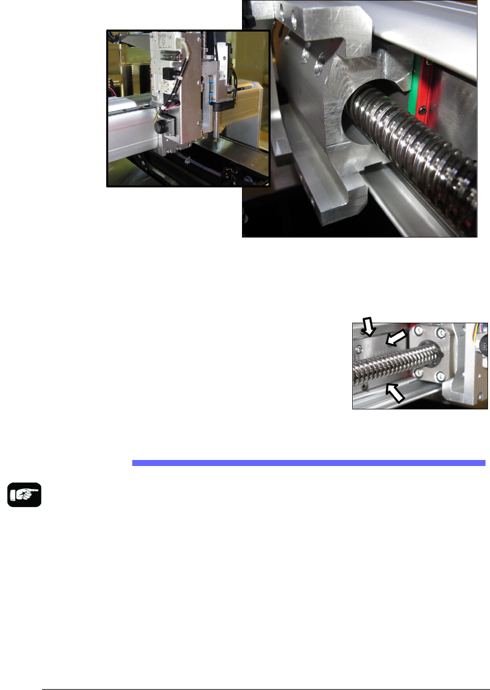
Figure 69: The Y-axis gantry ball screw and guide block, with cover
(left) and without.
3. Apply grease directly to the linear guide. Wipe off any excess.
4. Lubricate the Y-axis ball screw after
wiping off the old grease. Directly
apply new grease to the ball screw
sparingly. Wipe off any excess.
5. Replace all guards and shields.
Replacing a PNP Probe Assembly
Technicians trained on the PSV5000 can remove and re-install a Probe
Assembly if it is damaged or malfunctioning.
Requirement
• Metric hex key set (Long set with extended reach is best)
• Spare Probe Assembly
To remove a Probe Assembly
1. End a job and move the PNP head to the PARK position (click System
> Gantry > Tool) to move it to an accessible position.
2. Properly shut down the PSV5000 System; refer to Shutting Down the
PSV5000 System on page 38.
Pick and Place Probe Replacing a PNP Probe Assembly
PSV5000 Owner’s Manual - 115 -
CAUTION: Possible Machine Damage! The PNP head and gantry
can be damaged by pushing or pulling it improperly.
• When moving the head, only push or pull by gripping a gantry part and
not the head.
3. Remove the probe from the Probe stem. Refer to Installing the Correct
Probe in the PSV5000 Operator’s Manual.
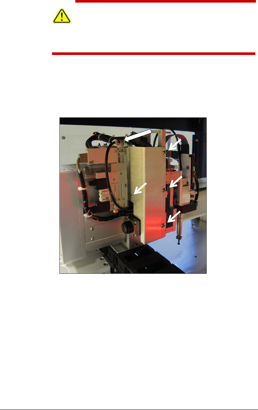
4. Disconnect the air hose form the vacuum generator (shown in the
figure below) by pushing on the collar while pulling the tubing.
Figure 70: Remove the air line at the One-Touch air connector at
the top of the assembly. Remove bracket fasters (arrows).
5. Remove the bracket with the vacuum generator attached; four
screws; three use 2.5 mm hex key, the back one uses 2 mm hex
key. See Figure 71: .
6. Unplug the ribbon cable from the back of the head assembly by
pulling down on the connector.