PSV5000_OwnersManual.pdf - 第120页
Maint enance ■ Pick and Place Prob e - 1 16 - D ata I/O ■ 096 - 0465 - 001C Figure 71: Unplu g the ribb on cable f rom the back . 7. Disconne ct the small co nnect at the t op of the assemble by pinch ing the clip and pu…
Pick and Place Probe Replacing a PNP Probe Assembly
PSV5000 Owner’s Manual - 115 -
CAUTION: Possible Machine Damage! The PNP head and gantry
can be damaged by pushing or pulling it improperly.
• When moving the head, only push or pull by gripping a gantry part and
not the head.
3. Remove the probe from the Probe stem. Refer to Installing the Correct
Probe in the PSV5000 Operator’s Manual.
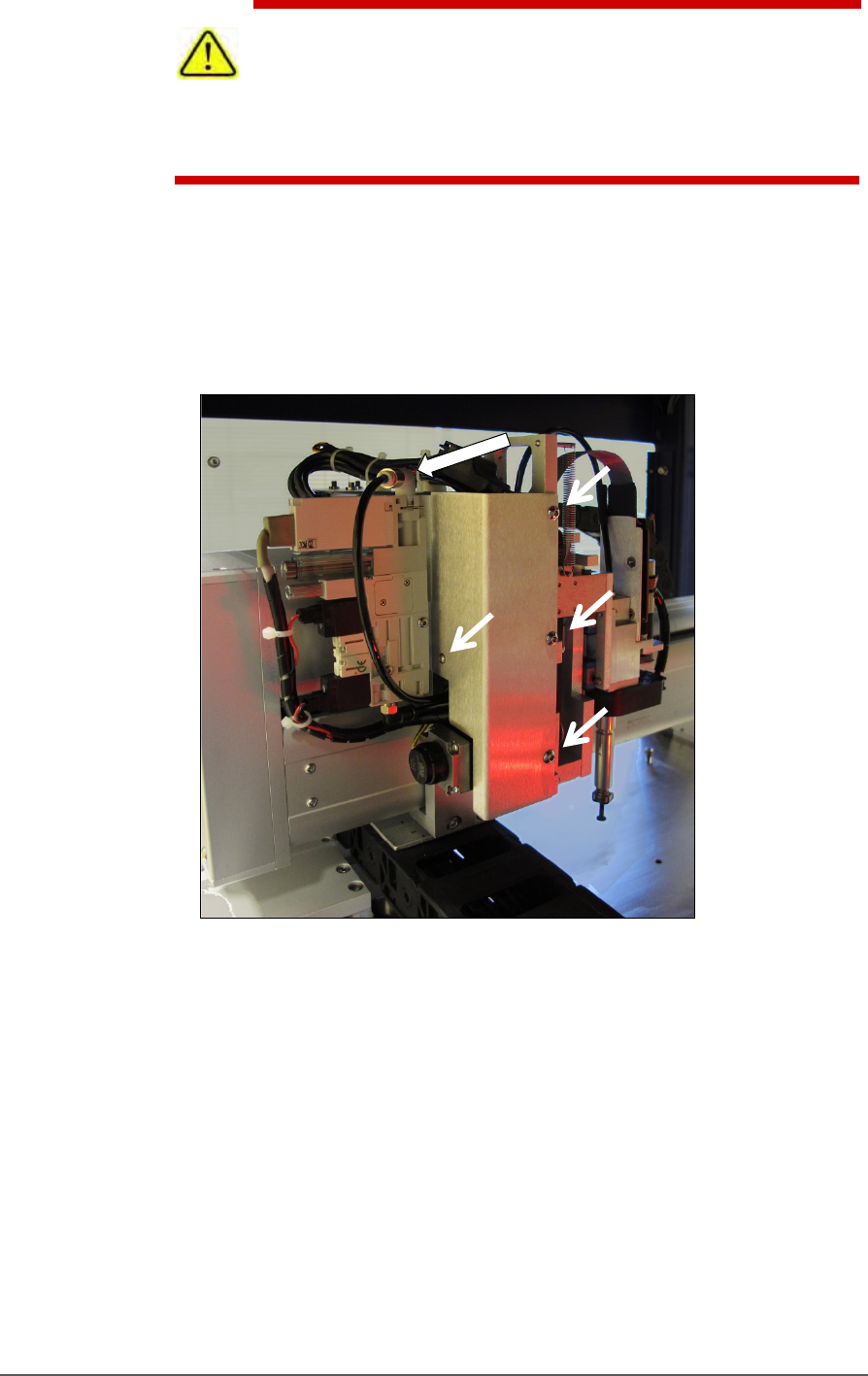
4. Disconnect the air hose form the vacuum generator (shown in the
figure below) by pushing on the collar while pulling the tubing.
Figure 70: Remove the air line at the One-Touch air connector at
the top of the assembly. Remove bracket fasters (arrows).
5. Remove the bracket with the vacuum generator attached; four
screws; three use 2.5 mm hex key, the back one uses 2 mm hex
key. See Figure 71: .
6. Unplug the ribbon cable from the back of the head assembly by
pulling down on the connector.
Maintenance ■ Pick and Place Probe
- 116 - Data I/O ■ 096-0465-001C
Figure 71: Unplug the ribbon cable from the back.
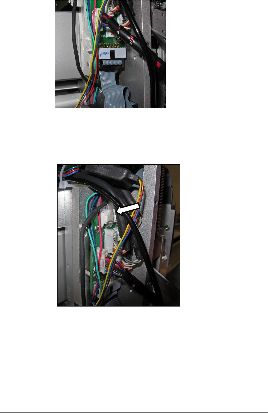
7. Disconnect the small connect at the top of the assemble by pinching
the clip and pulling up.
Figure 72: Top connector on the P robe Assembly.
8. Remove the four fasteners that hold the Probe Assembly to the PNP
head. Refer to Figure 71: (A long 2.5 mm hex key is required.)
9. Disconnect and remove the Z-axis retention spring (front side of
assembly).
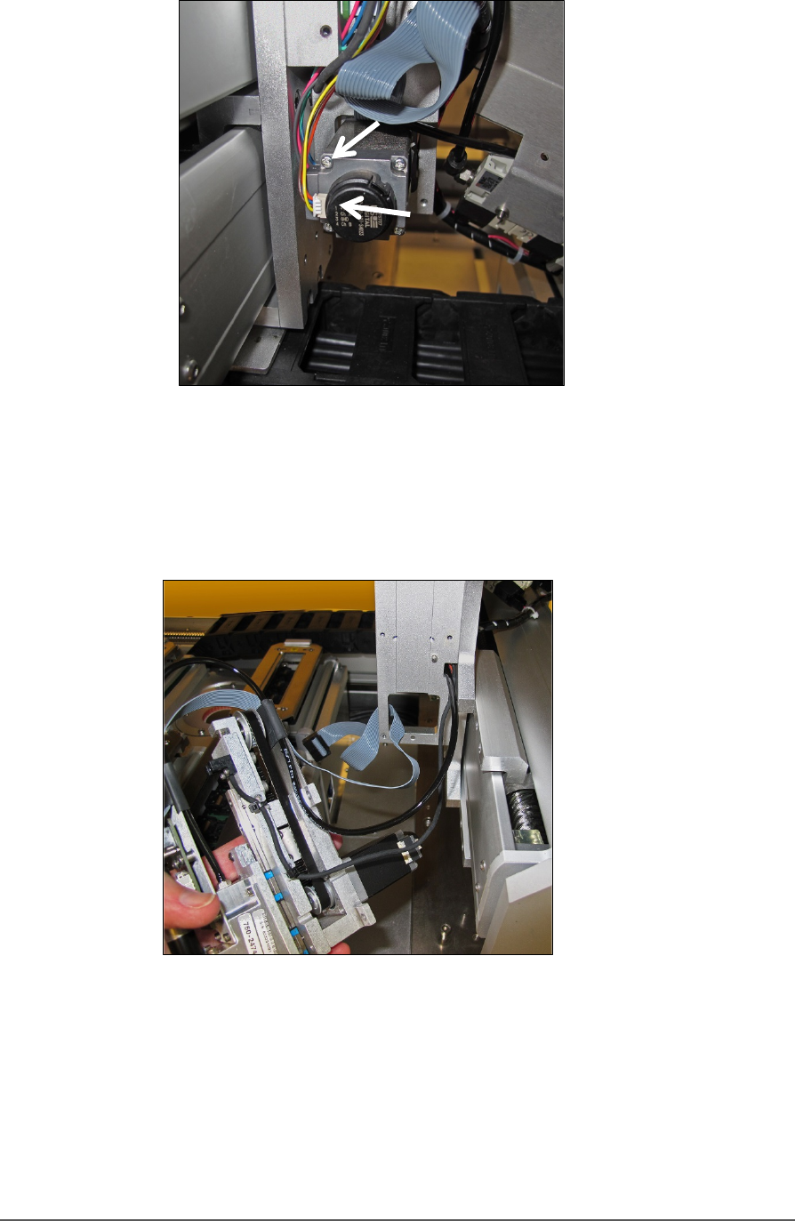
10. Remove two wire connectors from the back of the motor. See Figure
74: .
Pick and Place Probe Replacing a PNP Probe Assembly
PSV5000 Owner’s Manual - 117 -
Figure 73: Rear view of motor with two connectors (arrows). Note
that the yellow wire is on the bottom of the small connector.
11. Carefully pull the Probe Assembly with air tubing and wiring toward
the front of the machine.
Figure 74: Probe Assembly is removed with the tubing and wires
still through the head mount.
REINSTALLING THE PROBE ASSEMBLY
Generally, the reinstallation is in the reverse order of removal with these
precautions:
• Remember to thread the cables/tube through the head bracket.