PSV5000_OwnersManual.pdf - 第122页
Maint enance ■ Pick and Place Pro be - 118 - Data I/O ■ 096 - 0465 - 00 1 C • Ensure t he ribbon cabl e doesn’t get pinch ed behind t he probe assembly . • Make sure t he Prob e Assembly m ates up to t he locat ing pin o…
Pick and Place Probe Replacing a PNP Probe Assembly
PSV5000 Owner’s Manual - 117 -
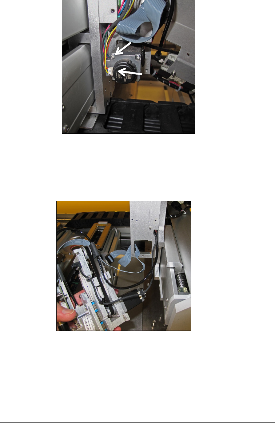
Figure 73: Rear view of motor with two connectors (arrows). Note
that the yellow wire is on the bottom of the small connector.
11. Carefully pull the Probe Assembly with air tubing and wiring toward
the front of the machine.
Figure 74: Probe Assembly is removed with the tubing and wires
still through the head mount.
REINSTALLING THE PROBE ASSEMBLY
Generally, the reinstallation is in the reverse order of removal with these
precautions:
• Remember to thread the cables/tube through the head bracket.

Maintenance ■ Pick and Place Probe
- 118 - Data I/O ■ 096-0465-001C
• Ensure the ribbon cable doesn’t get pinched behind the probe
assembly.
• Make sure the Probe Assembly mates up to the locating pin on the head
bracket.
• It’s easiest to connect the two motor wires after putting the head onto
the bracket but before screwing it in place.
• Make sure tubes and wires are securely stowed and fixed to avoid being
rubbed by any moving parts.
• Remember to re-install the retention spring.

Programmers FlashCORE Programmer Diagnostics
PSV5000 Owner’s Manual - 119 -
Programmers
FlashCORE programmers require some maintenance to continually
program at the highest yields.
Note: For LumenX Programmer diagnostics refer to Customer Letter
983-5085-001A. Check our website Technical Library.
It is NOT necessary to restart programmers between jobs.
FlashCORE Programmer Diagnostics
To optimize programming yields, voltages within the FlashCORE
programmer need to be calibrated once each year. This is a more
thorough HW test than the 'POST' (Power-On-Self-Test) as well as
ensuring that each programmer's precision reference is still within its
specified operating range.
Annual programmer Compliance Verification (CV) can be performed by
Data I/O at customer sites. This on-site visit is included if you have an
APS (Annual Programmer Support) contract (customer pays travel costs).
Optionally, customer can purchase a Diagnostic Adaptor Board (DAB)
and perform the compliance diagnostics themselves. Contact sales to
purchase a DAB.
Tools required
• Diagnostic Adapter Board (DAB), Data I/O part number 910-2200-003
(or higher).
This Diagnostic Adapter Board detects problems related to FlashCORE
(FC) programmer hardware failure. The DAB tests the Waveform Circuit
Board and Backplane Circuit Board. The DAB can also be used to locate
problems that have not yet shown symptoms.
The DAB performs these nine tests:
• Bus Test • Vpp Overcurrent Test
• Adapter ID Test • I2C Bus Test
• LED Driver Test • DAC Calibration Test
•
G Node Test • Gslew Test
• Vcc Overcurrent Test