PSV5000_OwnersManual.pdf - 第124页
Maint enance ■ Prog ramm ers - 120 - Data I/O ■ 096 - 046 5 - 00 1C The wri st strap D ata I/O PN is 440 - 0021 - 001. R UNNING THE P ROGRAMMER D IA GNOSTIC T EST To run diagn ostic tests on Fl ashCORE progr ammer(s): 1.…

Programmers FlashCORE Programmer Diagnostics
PSV5000 Owner’s Manual - 119 -
Programmers
FlashCORE programmers require some maintenance to continually
program at the highest yields.
Note: For LumenX Programmer diagnostics refer to Customer Letter
983-5085-001A. Check our website Technical Library.
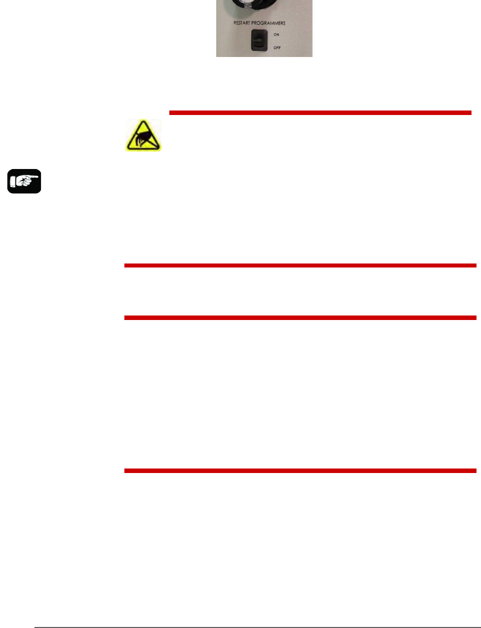
It is NOT necessary to restart programmers between jobs.
FlashCORE Programmer Diagnostics
To optimize programming yields, voltages within the FlashCORE
programmer need to be calibrated once each year. This is a more
thorough HW test than the 'POST' (Power-On-Self-Test) as well as
ensuring that each programmer's precision reference is still within its
specified operating range.
Annual programmer Compliance Verification (CV) can be performed by
Data I/O at customer sites. This on-site visit is included if you have an
APS (Annual Programmer Support) contract (customer pays travel costs).
Optionally, customer can purchase a Diagnostic Adaptor Board (DAB)
and perform the compliance diagnostics themselves. Contact sales to
purchase a DAB.
Tools required
• Diagnostic Adapter Board (DAB), Data I/O part number 910-2200-003
(or higher).
This Diagnostic Adapter Board detects problems related to FlashCORE
(FC) programmer hardware failure. The DAB tests the Waveform Circuit
Board and Backplane Circuit Board. The DAB can also be used to locate
problems that have not yet shown symptoms.
The DAB performs these nine tests:
• Bus Test • Vpp Overcurrent Test
• Adapter ID Test • I2C Bus Test
• LED Driver Test • DAC Calibration Test
•
G Node Test • Gslew Test
• Vcc Overcurrent Test
Maintenance ■ Programmers
- 120 - Data I/O ■ 096-0465-001C
The wrist strap Data I/O
PN is 440-0021-001.
RUNNING THE PROGRAMMER DIAGNOSTIC TEST
To run diagnostic tests on FlashCORE programmer(s):
1. Finish a job if one is running; wait for the PNP head to park.
2. Turn OFF the programmer circuit breaker at the Power Panel (down
position).
3. Exit CH700 to return to TaskLink.
WARNING: ESD hazard! To prevent ESD shock, before you
touch the Socket Adapter, discharge static electricity from
yourself by touching a common ground or an unpainted metal
surface.
When at the PSV5000 Machine, always wear a wrist strap containing a 1
M-ohm min. to 10 M-ohm max. current limiting resistor. Connect the
antistatic wrist strap to the grounding socket on the front or back of the
PSV5000 Machine.
WARNING: Possible collision hazard! The high speed and force of the gantry
can seriously harm anyone working inside the workspace.
When working within the machine workspace, moving the PNP head must
be the responsibility of only one qualified individual. All others must stay
clear of the machine controls to prevent injury to that person.
Ensure that a job is Paused or Finished, or the system power is OFF prior to
opening any safety doors.
4. Remove the Socket Adapter from the target programmer and insert the
Diagnostic Adapter Board, ensuring that it aligns correctly on the adapter
pins. Screw down the two bracket screws (4 mm hex key).
5. Turn the programmer circuit breaker at the Power Panel ON (up
position).
6. Start TaskLink and click Tools > Run Programmer Diagnostics.

Programmers Replacing a Programmer
PSV5000 Owner’s Manual - 121 -
7. On the Diagnostics window, select the programmer with the DAB
installed.
8. Click Test All.
The pass/fail test results are displayed in TaskLink and are also written
to /fdrroot/system/diaglog.txt (and to the CF-card of the target
FlashCORE programmer). These files can be viewed in TaskLink and
saved (on the Handler Computer).
If any of the tests show Fail in the TaskLink display, contact your nearest
Data I/O Service Center for repair options. To help our service personnel
diagnose the problem, please e-mail both the
eventlog.txt and diaglog.txt files.
Sample dialog.txt file:
Diagnostic Pass #1
Run Vpp Overcurrent test.
DUT 1 G1 Vpp overcurrent is sensed at 57 mA.
DUT 1 G2 Vpp overcurrent is sensed at 57 mA.
DUT 1 G3 Vpp overcurrent is sensed at 57 mA.
DUT 1 G4 Vpp overcurrent is sensed at 57 mA.
DUT 2 G1 Vpp overcurrent is sensed at 57 mA.
DUT 2 G2 Vpp overcurrent is sensed at 57 mA.
DUT 2 G3 Vpp overcurrent is sensed at 57 mA.
DUT 2 G4 Vpp overcurrent is sensed at 57 mA.
Error: DUT 3 G1 Vpp overcurrent is not sensed from 50 mA to 70
mA.
Error: DUT 3 G2 Vpp overcurrent is not sensed from 50 mA to 70
mA.
Error: DUT 3 G3 Vpp overcurrent is not sensed from 50 mA to 70
mA.
Error: DUT 3 G4 Vpp overcurrent is not sensed from 50 mA to 70
mA.
DUT 4 G1 Vpp overcurrent is sensed at 57 mA.
DUT 4 G2 Vpp overcurrent is sensed at 57 mA.
DUT 4 G3 Vpp overcurrent is sensed at 57 mA.
DUT 4 G4 Vpp overcurrent is sensed at 57 mA.
Diagnostics failed.