PSV5000_OwnersManual.pdf - 第127页
Prog ramme rs Replac ing a P r ogramme r PSV5000 O wner ’s M anual - 123 - Figure 75: The right side c onnection panel insid e the rig ht front access do or. Power cables (bla ck arrow), Pneumatic manifol d (whit e a…
Maintenance ■ Programmers
- 122 - Data I/O ■ 096-0465-001C
Replacing a Programmer
If a programmer is not working properly, it can be removed and replaced
with another one. Within these instructions are notices where steps differ
for LumenX programmers—denoted by the logo.
TOOLS REQUIRED
• Cable Tie tool
• Clippers to cut cable tie
• 3 mm hex key (Allen wrench)
• Access door key that came with your PSV5000
WARNING: Electric shock hazard! Injury or death may result
from contact to parts inside the machine. Shut off the PSV5000
System by turning OFF the main power switch before working
on or near the gantry, before opening any access doors or removing any
cabinet panels.
To remove a FlashCORE programmer:
1. Properly turn OFF the PSV5000 sub-systems and machine power.
See Shutting Down the PSV5000 System on page 38.
2. With the supplied door key, open the lower, right front access door.
3. Locate the target programmer and follow the heavy gray power cable
to the connection panel on the right side of the machine. Refer to the
figures below.
4. Mark the cable (to re-install in the same place) and pull the
connector straight out from the PCB. LumenX programmers
have two connectors per programmer—mark and disconnect both.
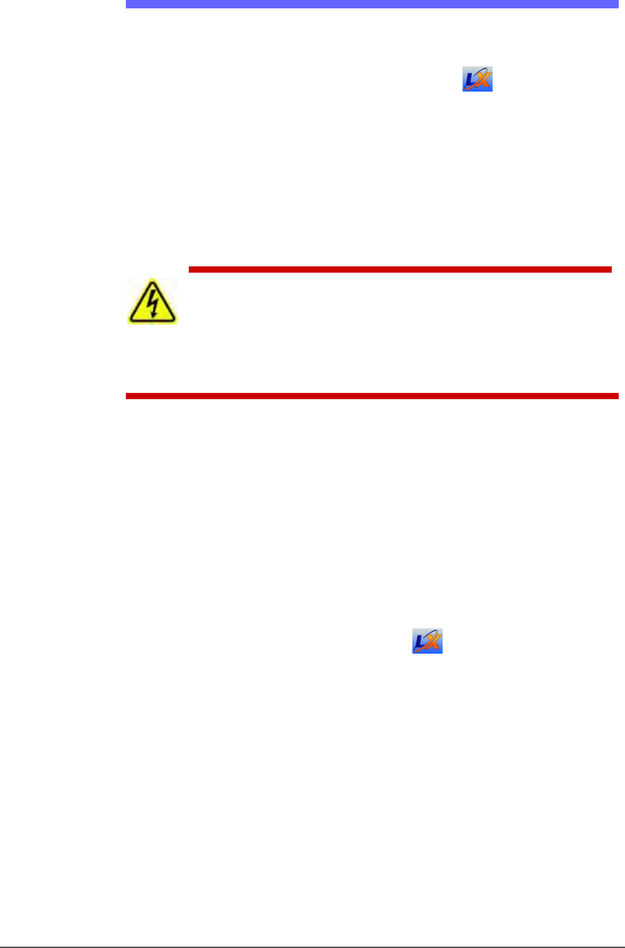
Programmers Replacing a Programmer
PSV5000 Owner’s Manual - 123 -
Figure 75: The right side connection panel inside the right front
access door. Power cables (black arrow), Pneumatic manifold
(white arrow),
and the Ethernet connections (circled).
For LumenX, there is another separate Ethernet router, not
shown in this view.
5. Follow and mark the thin shiny black tubing to the air manifold on
the right mounting plate.
6. Disconnect the air tubing at the one-touch connector elbow (push in
on the collar while pulling the tube out).
Note: Manifold port plugs must be installed into all ports that will not be
used.
7. Follow and mark the Ethernet cable to the router :
on the right mounting plate (FlashCORE programmers).
mounted nearby (LumenX programmers).
8. Disconnect the Ethernet cable by pinching the clip and pulling up.
Refer to Figure 76: .
Maintenance ■ The Laser Module and Shuttle
- 124 - Data I/O ■ 096-0465-001C
9. Remove four screws (3 mm hex key) from the bottom side of the
programmer (two nearside, two farside). One screw might also hold a
cable tie which must be cut first. Save the cable tie mount for reuse
(as well as the screws).
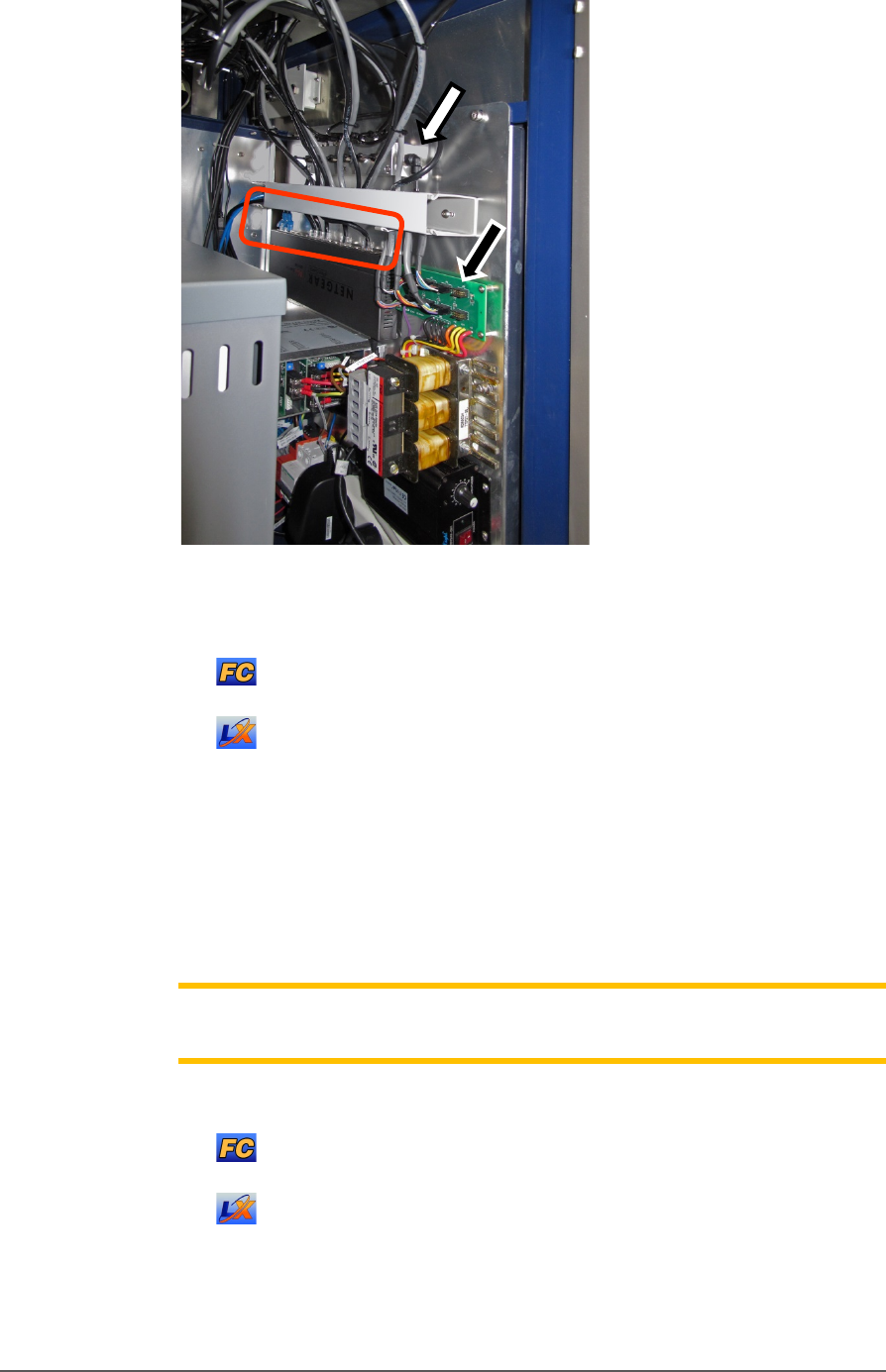
Figure 76: Inside the machine looking up at the programmers.
There are four attachment screws (circled) per programmer.
FlashCORE shown, but LumenX is similar, with screws
farther apart.
10. Open the front or back safety door to access the workspace.
11. Lift up on the target programmer being cautious of the cables that will
come out with it.
Replacement is in the reverse order of removal.
The Laser Module and Shuttle
[Laser Marking only] Laser Marker System is optional equipment on
your PSV5000 Programming System. The Laser Module employs a laser
shuttle (except when using Tape Output) and includes a fume extractor.
The Laser Module
The Laser shuttle transports devices to and from the lasing area.
REQUIREMENTS
• Disposable gloves and protective goggles
• Sealable Plastic bags