PSV5000_OwnersManual.pdf - 第128页
Maint enance ■ The Laser Mod ule and Shuttl e - 1 24 - Data I/O ■ 096 - 0465 - 00 1C 9. Remove fo ur screws (3 mm hex k ey) from the bott om side of the progr ammer (two nearside, two farside). One scre w migh t also hol…
Programmers Replacing a Programmer
PSV5000 Owner’s Manual - 123 -
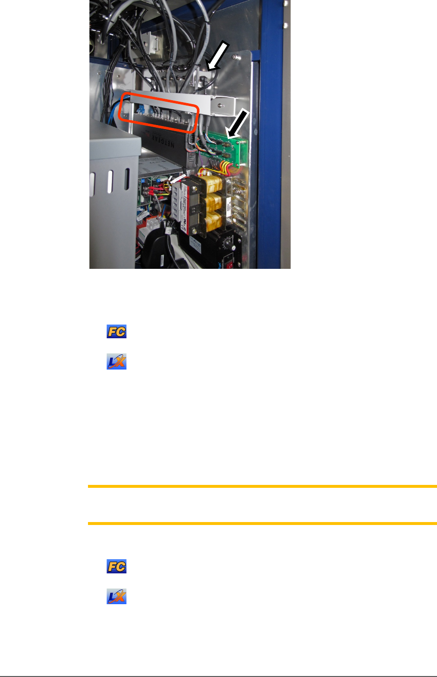
Figure 75: The right side connection panel inside the right front
access door. Power cables (black arrow), Pneumatic manifold
(white arrow),
and the Ethernet connections (circled).
For LumenX, there is another separate Ethernet router, not
shown in this view.
5. Follow and mark the thin shiny black tubing to the air manifold on
the right mounting plate.
6. Disconnect the air tubing at the one-touch connector elbow (push in
on the collar while pulling the tube out).
Note: Manifold port plugs must be installed into all ports that will not be
used.
7. Follow and mark the Ethernet cable to the router :
on the right mounting plate (FlashCORE programmers).
mounted nearby (LumenX programmers).
8. Disconnect the Ethernet cable by pinching the clip and pulling up.
Refer to Figure 76: .
Maintenance ■ The Laser Module and Shuttle
- 124 - Data I/O ■ 096-0465-001C
9. Remove four screws (3 mm hex key) from the bottom side of the
programmer (two nearside, two farside). One screw might also hold a
cable tie which must be cut first. Save the cable tie mount for reuse
(as well as the screws).
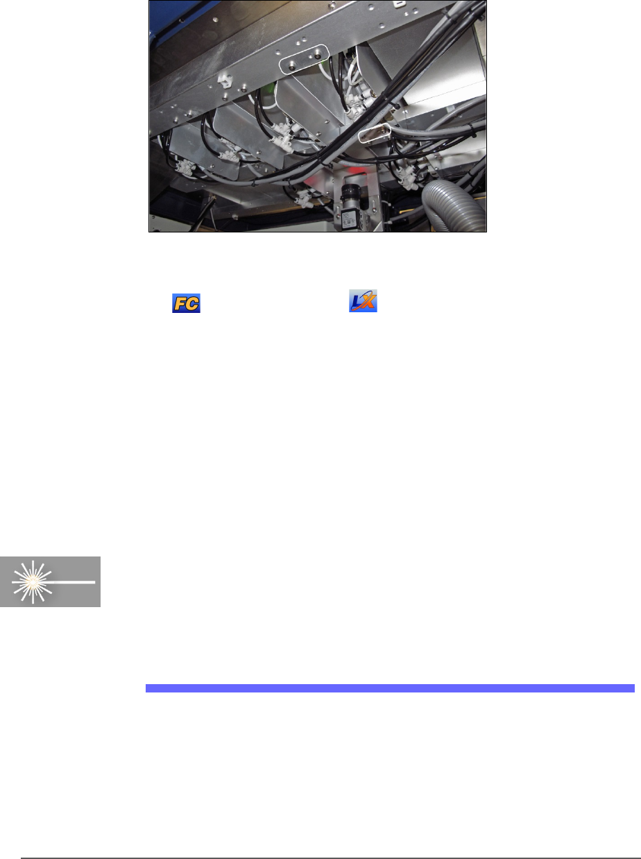
Figure 76: Inside the machine looking up at the programmers.
There are four attachment screws (circled) per programmer.
FlashCORE shown, but LumenX is similar, with screws
farther apart.
10. Open the front or back safety door to access the workspace.
11. Lift up on the target programmer being cautious of the cables that will
come out with it.
Replacement is in the reverse order of removal.
The Laser Module and Shuttle
[Laser Marking only] Laser Marker System is optional equipment on
your PSV5000 Programming System. The Laser Module employs a laser
shuttle (except when using Tape Output) and includes a fume extractor.
The Laser Module
The Laser shuttle transports devices to and from the lasing area.
REQUIREMENTS
• Disposable gloves and protective goggles
• Sealable Plastic bags
The Laser Module and Shuttle The Laser Module
PSV5000 Owner’s Manual - 125 -
• Antistatic cleaner
• Cloth Paper towels
HOUSING
WARNING: Possible health hazard! Lased materials can
contain hazardous toxins in the dust that cause eye and skin damage! DO
NOT use compressed air to remove laser dust or any method that allows the
particulate to be released into the work environment. Wear safety goggles
and disposable protective gloves.
1. Properly shut off the PSV5000 sub-systems and machine power. See
Shutting Down the PSV5000 System on page 38.
2. Wear eye protection and put on disposable protective gloves.
3. Use a damp cloth or paper towel and antistatic cleaner to wipe laser
marking dust and other foreign material from the housing.
4. Place paper towels, cloth, and protective gloves into a sealable plastic
bag. Seal the bag and dispose of as hazardous waste. Remove safety
goggles.
WARNING: Possible health hazard from toxic materials! Government
regulations apply to the storage of hazardous waste. Ensure that
contaminated filters are:
• properly labeled and stored in your hazardous waste storage area
• not stored on your site longer than government regulations allow (the
typical limit is 90 days)—check your government regulations for hazardous
waste storage requirements.
CLEANING THE LASER SHUTTLE TIP
Dirty tips may cause air leakage. Cleaning intervals depend on amount of
use.
To clean the tips:
1. If machine power in ON, move the head: either
At the Run window: click Pause or Finish.
Or at the Gantry window: click Park or Tool.
2. Open the safety doors.