PSV5000_OwnersManual.pdf - 第145页
T ape Output Syst em Mai nte nanc e Cle aning the Press ure Sea l PSV5000 O wner ’s M anual - 141 - To clean the Pr essure Seal Ta pe Output Syst em: 1. Turn O N the PSV 5000 System p ower and air. 2. Start Ta skL in…
Maintenance ■ Tape Output System Maintenance
- 140 - Data I/O ■ 096-0465-001C
Your PSV5000 System will continue to operate as normal on the
backup drive. However, the failed drive must be replaced for
continued safety.
After the failed drive is identified and replaced, the message on-screen
will read REBUILDING. After it has rebuilt, the next time you start up it
will read NORMAL.
Contact Data I/O Support or your nearest Data I/O representative.
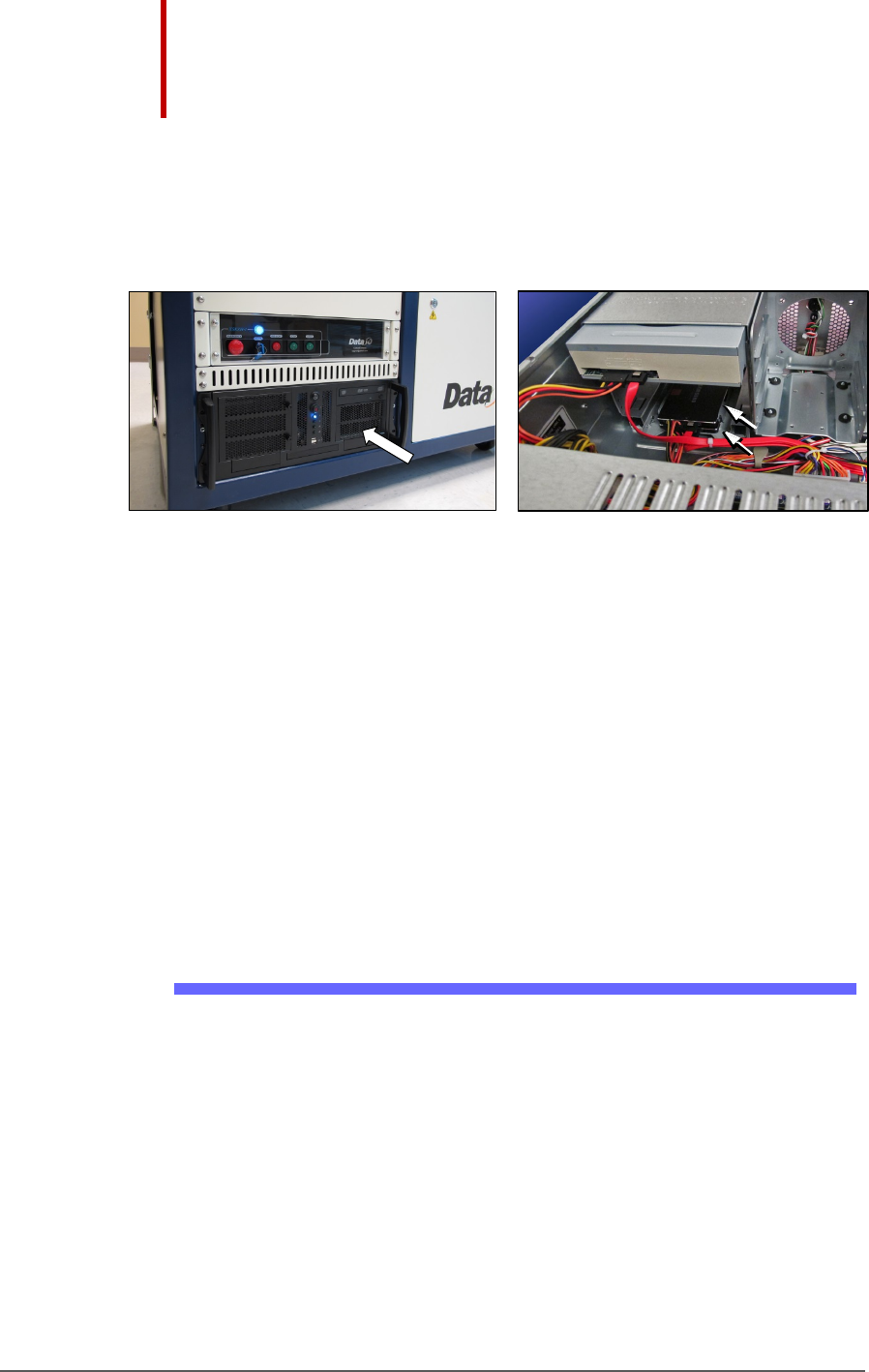
Figure 81: The RAID solid state hard drives are inside the Handler
PC case. The Handler PC must be removed to access the RAID
backup drives. In image B, the Handler PC cover has been
removed: this image is a representation only for reference.
Tape Output System Maintenance
The Tape Output System is an optional system for placing and taping
programmed devices into device tape.
Items not covered here can be found in the TM-50 Taping Module User’s
Guide that came with your PSV5000 System.
Cleaning the Pressure Seal
The Pressure Seal Tape Output System requires cleaning to prevent
problems with breaking the device tape or tearing the tape sprocket
holes. Cleaning removes build up from the cover tape application rollers
and the drive sprocket top pressure idler wheel.
CLEANING TOOLS REQUIRED
• Dry or damp shop towel
• A reel of empty device tape (carrier tape)
• A reel of cover tape
B
Tape Output System Maintenance Cleaning the Pressure Seal
PSV5000 Owner’s Manual - 141 -
To clean the Pressure Seal Tape Output System:
1. Turn ON the PSV5000 System power and air.
2. Start TaskLink.
3. Select a job that requires the use of the tape output.
4. Click Run (and Yes or OK to subsequent dialogs), which opens
CH700 automatically.
5. Click Start.
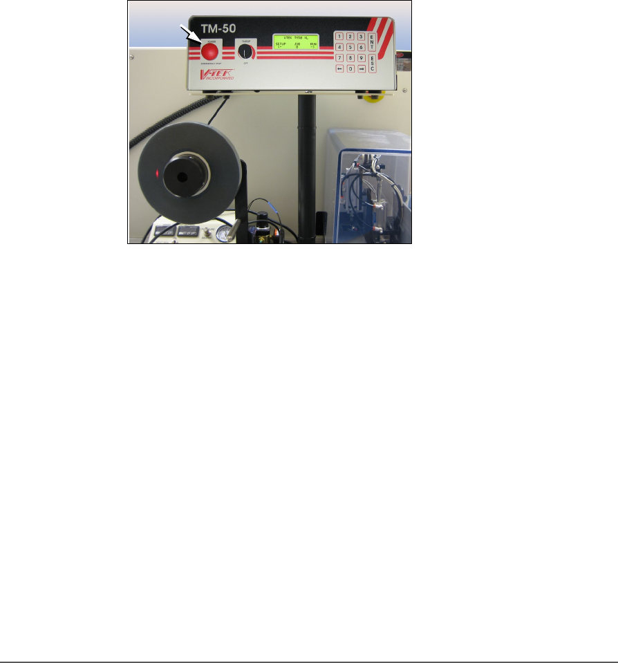
6. Turn on the Tape Output Controller by pushing the red Power
button. Refer to the figure below.
7. At the V-TEK start-up screen, select Setup by pressing the left arrow
button.
Figure 82: Tape Output Module Controller. The arrow points to the
Power On/Off button which is also the Emergency-Stop (for the
Tape-Out Module only!).
8. Configure the Tape Output Controller by setting the following:

Maintenance ■ Tape Output System Maintenance
- 142 - Data I/O ■ 096-0465-001C
AT THE SETUP MENU:
• reset Count Stop to desired amount:
Press 1, to re-zero the present count
Press 2, then enter the desired number, then press the
ENT button.
• select the desired device tape pitch from the Pitch
Selection menu. Then press ENT.
The pitch can be determined by using the pitch setting decal
located on the loading track or the pitch setting guide found at the
front of the TM-50 Taping Module User’s Guide.
AT THE ADVANCE MENU:
• set the number of pockets to advance to 1. Then press
ENT.
AT THE SPEED MENU:
• set the advance speed between 40 to 100 depending on
the device tape width and device size. Then press ENT.
NOTE: Prevent device tape breakage and advancement problems
with narrower tape widths by setting slower speeds— in range
40 to 60.
Higher speeds may cause the devices to be dislodged from the
pockets or may cause the sprocket holes on the tape to rip out.
AT THE JOG MENU
• jog the device tape forward to align the pocket with the
PNP head.
AT THE MODE MENU
• select PSA mode for pressure seal cover tape. An asterisk
indicates the current setting. Then press ESC.
NOTE: The Heat Seal switch should be OFF.
AT THE RUN MENU
• select Run Mode. The run window displays all the