PSV5000_OwnersManual.pdf - 第148页
Maint enance ■ T ape Output Syst em Main te nance - 14 4 - Data I/O ■ 096 - 0465 - 0 0 1C c. Wipe the idler clean. d. Reinstall the dry O -R ing s onto t he idler . Adjus ting Pr essure of the PSA Seal Rolle rs 1. Advanc…
Tape Output System Maintenance Cleaning the Pressure Seal
PSV5000 Owner’s Manual - 143 -
selected setup parameters.
• verify all settings for accuracy.
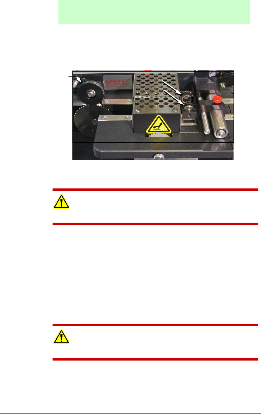
9. Inspect the PSA seal rollers for build up of grime from the cover tape.
See the figure below.
Figure 83: On the Tape Out Module, the PSA Seal Rollers (arrows)
and Sprocket Idler with O-Rings.
CAUTION: Possible Machine Damage! Do not use solvents other than
alcohol when cleaning the black polyurethane wheels.
10. If grime buildup exists on the PSA Seal rollers—
a. Using a shop towel and alcohol or alcohol wipes, clean the
build up from the cover tape application rollers. Hold the
alcohol cloth on the roller and rotate the roller 360°.
b. Repeat procedure for the other application roller.
11. Inspect the drive sprocket top idler and rubber O-Rings for any build
up from the cover tape. See the figure above.
12. If grime buildup exists on the idler and O-Rings—
CAUTION: O-Rings might be easily damaged. Handle gently to avoid
breaking them.
a. Gently remove the two O-Rings from the drive sprocket idler.
b. Using a damp cloth or a commercial wipe, remove all grime
from O-Rings.
O-rings

Maintenance ■ Tape Output System Maintenance
- 144 - Data I/O ■ 096-0465-001C
c. Wipe the idler clean.
d. Reinstall the dry O-Rings onto the idler.
Adjusting Pressure of the PSA Seal Rollers
1. Advance the device tape with the cover tape through the Seal Rollers
using the manual advance pedal. Advance enough pockets to
correctly align the cover tape on the carrier tape.
2. Perform a peel back test by peeling the cover tape from the carrier
tape. Notice how well the cover tape adheres to the device tape.
Perform a twist test by giving the tape a slight twist. Notice if the
cover tape detaches from the device tape.
If either test produces loose cover tape, increase the application
roller pressure by screwing the PSA Seal pressure adjustment screw
in (clockwise).
If both tests look acceptable, visually inspect the sealed device tape
for adhesive that may have been squeezed out during application. If
adhesive is visible, the Seal Roller pressure is too high. Decrease the
application roller pressure by screwing the PSA Seal pressure
adjustment screw out and retest.
Troubleshooting the Tape Output System
The Tape Output System contains sensors that detect these fault
conditions:
• a device is on top the device tape (carrier tape)—Track Jam
Sensor
• no cover tape is on the reel—Cover Tape Sensor
• device tape is not properly inserted in the device tape
track—Device Tape Present Sensor
• a pocket in the carrier tape is empty—Pocket Empty Sensor
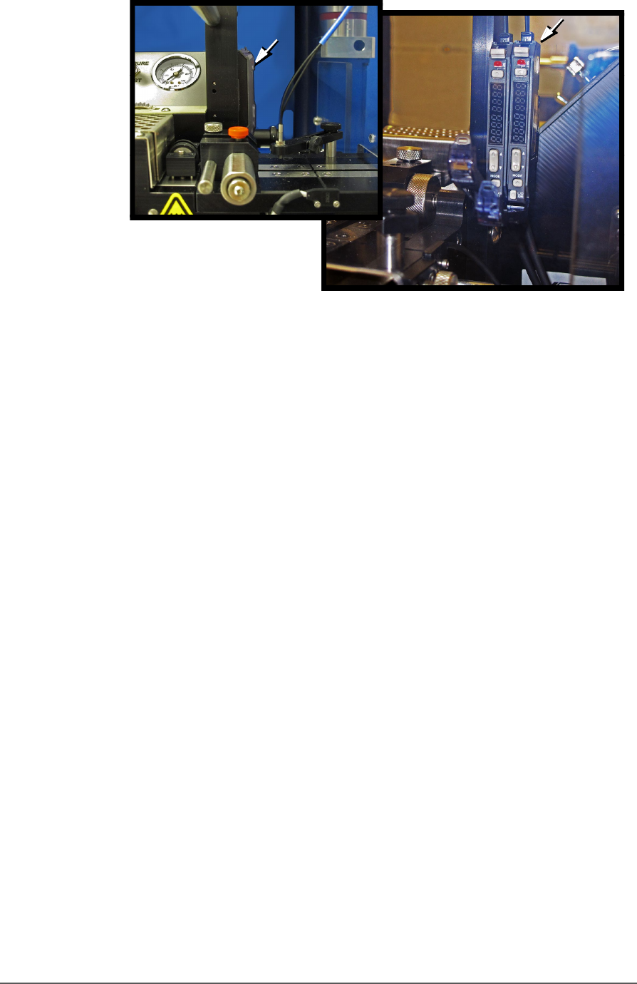
When the CH700 software displays the error message Tape Out Unit,
one of the tape output system sensors has been triggered. The most
likely sensors to trigger are the Device Jam and Device Tape sensors. See
figure below.
Tape Output System Maintenance Troubleshooting the Tape Output System
PSV5000 Owner’s Manual - 145 -
Figure 84: Optical Fiber Amplifiers: Cover Tape Present and Empty
Pocket, respectively. Amplifier doors are open in the right side
view.
Fr ont Vi ew
Right Side View