PSV5000_OwnersManual.pdf - 第149页
T ape Output Syst em Mai nte nanc e T roubleshooting the T ape Output System PSV5000 O wner ’s M anual - 145 - Figure 84: Opti cal Fiber Amplifier s : Cover T ape Prese nt and E mpty Pocket, respectivel y. Amplif ier…

Maintenance ■ Tape Output System Maintenance
- 144 - Data I/O ■ 096-0465-001C
c. Wipe the idler clean.
d. Reinstall the dry O-Rings onto the idler.
Adjusting Pressure of the PSA Seal Rollers
1. Advance the device tape with the cover tape through the Seal Rollers
using the manual advance pedal. Advance enough pockets to
correctly align the cover tape on the carrier tape.
2. Perform a peel back test by peeling the cover tape from the carrier
tape. Notice how well the cover tape adheres to the device tape.
Perform a twist test by giving the tape a slight twist. Notice if the
cover tape detaches from the device tape.
If either test produces loose cover tape, increase the application
roller pressure by screwing the PSA Seal pressure adjustment screw
in (clockwise).
If both tests look acceptable, visually inspect the sealed device tape
for adhesive that may have been squeezed out during application. If
adhesive is visible, the Seal Roller pressure is too high. Decrease the
application roller pressure by screwing the PSA Seal pressure
adjustment screw out and retest.
Troubleshooting the Tape Output System
The Tape Output System contains sensors that detect these fault
conditions:
• a device is on top the device tape (carrier tape)—Track Jam
Sensor
• no cover tape is on the reel—Cover Tape Sensor
• device tape is not properly inserted in the device tape
track—Device Tape Present Sensor
• a pocket in the carrier tape is empty—Pocket Empty Sensor
When the CH700 software displays the error message Tape Out Unit,
one of the tape output system sensors has been triggered. The most
likely sensors to trigger are the Device Jam and Device Tape sensors. See
figure below.

Tape Output System Maintenance Troubleshooting the Tape Output System
PSV5000 Owner’s Manual - 145 -
Figure 84: Optical Fiber Amplifiers: Cover Tape Present and Empty
Pocket, respectively. Amplifier doors are open in the right side
view.
Fr ont Vi ew
Right Side View
Maintenance ■ Tape Output System Maintenance
- 146 - Data I/O ■ 096-0465-001C
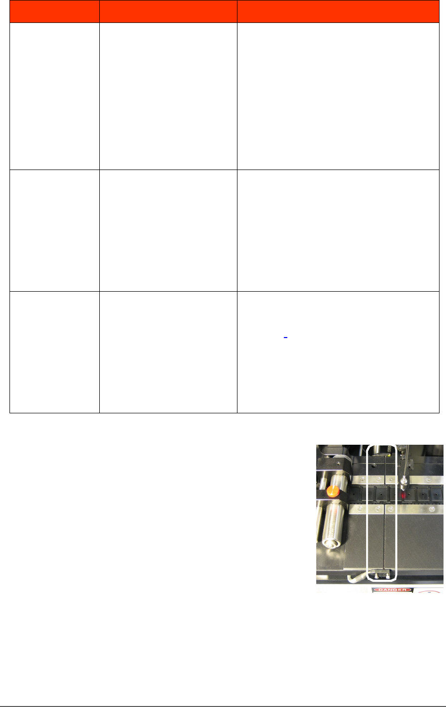
The Tra ck Jam sensor
Lamp Color Error Messages Possible Resolution
None
TRACK JAM SENSOR
Tape Out Unit error message
displays and a red LED
lights in the Device Jam
Sensor.
• Use a vacuum tool to seat the device in
the device tape pocket.
• Re-seat the device tape in the Adjustable
Loading Track.
• Use air to blow any debris out of the
Device Jam sensor path.
• Adjust the Device Jam Sensor Controller.
See Track Jam Sensor and Controller
on page 146.
None
COVER TAPE SENSOR
AND
AMPLIFIER
Error message on the Tape
Out Unit displays and a red
LED is illuminated in the
Cover Tape Sensor amplifier
(left amplifier).
• Replace the empty cover tape reel with a
full one.
• If the reel still contains cover tape, adjust
the Cover Tape Sensor Controller. See
Track Jam Sensor and Controller
• on page 146.
None
POCKET EMPTY SENSOR
AND
AMPLIFIER
A Tape Out Unit error
message displays and a red
LED is illuminated on the
Pocket Empty Sensor
amplifier.
• Adjust the pocket-Empty Sensor. See
“Adjust the Pocket-Empty Sensor as
follows:
” on the next page
TRACK JAM SENSOR AND CONTROLLER
The Track Jam sensor detects when a
device is not properly seated in the pocket.
This sensor is located on the Adjustable
Loading Track immediately before the
carrier tape enters the cover taping area.
COVER TAPE SENSOR AND AMPLIFIER
The Cover Tape sensor detects when there
is no cover tape on the reel. When the Cover Tape sensor is triggered, a
red LED is illuminated in the Cover Tape Sensor Controller.