PSV5000_OwnersManual.pdf - 第151页
T ape Output Syst em Mai nte nanc e T roubleshooting the T ape Output System PSV5000 O wner ’s M anual - 147 - A DJUSTING THE C OVE R T APE S EN SOR C ONTROL LER 1. Ensure that the Ou tput Sel ecto r mode is set to D…
Maintenance ■ Tape Output System Maintenance
- 146 - Data I/O ■ 096-0465-001C
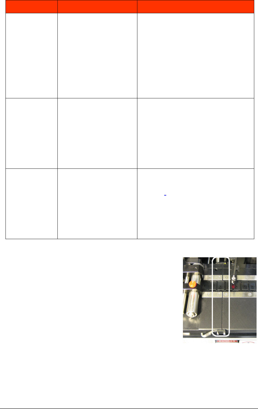
The Tra ck Jam sensor
Lamp Color Error Messages Possible Resolution
None
TRACK JAM SENSOR
Tape Out Unit error message
displays and a red LED
lights in the Device Jam
Sensor.
• Use a vacuum tool to seat the device in
the device tape pocket.
• Re-seat the device tape in the Adjustable
Loading Track.
• Use air to blow any debris out of the
Device Jam sensor path.
• Adjust the Device Jam Sensor Controller.
See Track Jam Sensor and Controller
on page 146.
None
COVER TAPE SENSOR
AND
AMPLIFIER
Error message on the Tape
Out Unit displays and a red
LED is illuminated in the
Cover Tape Sensor amplifier
(left amplifier).
• Replace the empty cover tape reel with a
full one.
• If the reel still contains cover tape, adjust
the Cover Tape Sensor Controller. See
Track Jam Sensor and Controller
• on page 146.
None
POCKET EMPTY SENSOR
AND
AMPLIFIER
A Tape Out Unit error
message displays and a red
LED is illuminated on the
Pocket Empty Sensor
amplifier.
• Adjust the pocket-Empty Sensor. See
“Adjust the Pocket-Empty Sensor as
follows:
” on the next page
TRACK JAM SENSOR AND CONTROLLER
The Track Jam sensor detects when a
device is not properly seated in the pocket.
This sensor is located on the Adjustable
Loading Track immediately before the
carrier tape enters the cover taping area.
COVER TAPE SENSOR AND AMPLIFIER
The Cover Tape sensor detects when there
is no cover tape on the reel. When the Cover Tape sensor is triggered, a
red LED is illuminated in the Cover Tape Sensor Controller.

Tape Output System Maintenance Troubleshooting the Tape Output System
PSV5000 Owner’s Manual - 147 -
ADJUSTING THE COVER TAPE SENSOR CONTROLLER
1. Ensure that the Output Selector
mode is set to D.ON by pressing
the Mode button. (There may be
an L/D ON button or toggle to
change the mode.)
2. Install a roll of cover tape onto
the spindle.
3. Press and release the SET button
in the left amplifier.
4. Remove the cover tape.
5. Press and release the SET button again.
NOTE: If an error occurs or the sensor fails to detect the cover tape after
switching from a different type of cover tape, then the Cover Tape sensor
may need to be re-taught to sense that particular type of cover tape.
POCKET EMPTY SENSOR AND AMPLIFIER
The Pocket Empty sensor alerts the operator when a pocket is empty as
the device tape approaches the cover taping location.
ADJUST THE POCKET-EMPTY SENSOR AS FOLLOWS:
1. Set the track width for the target device tape
A) loosen the two Track Width Lock knobs,
B) pull or push the side nearest the operator to correct
width,
C) tighten lock knobs.
2. Load a roll of device tape onto the spindle and into the track.
3. Loosen the knob on the left side of the Pocket Empty Sensor
bracket to adjust the height above the tape. Retighten.
4. Loosen the knob on top to center the sensor on the tape.
Retighten.
5. Advance the tape until a pocket with a device in it is centered
under the sensor.
6. Ensure that the Output Selector mode on the middle amplifier is
set to D.ON by pressing the Mode button. (There may be an L/D
ON button or toggle to change the mode.)
7. Press and release the SET button in the right amplifier.
8. Remove the device from the tape pocket.

Maintenance ■ The Tray Feeder
- 148 - Data I/O ■ 096-0465-001C
9. Press and release the SET button again.
NOTE: The Pocket-Empty Sensor must be reset for each new device type
to be taped.
The Tray Feeder
The Automatic Tray Feeder is optional equipment to the
PSV5000 System. It is a high-speed tray exchanger, delivering JEDEC
trays to pick and place positions.
Information not found here, but important, can be found in the Tray
Feeder Operation Manual, such as the location of possible pinch points.
Cleaning and Inspecting the Tray Feeder
[Tray Feeder only]
1. Stop or Pause a job if one is running.
2. Check the automatic Tray Feeder for damaged or broken parts and
replace as necessary.
3. Visually inspect the shuttle belts for dirt, nicks, or other signs of
damage.
4. If the shuttle belts are dirty, clean with dry, compressed air and wipe
with a dry, lint-free cloth and isopropyl alcohol.
5. Check that the shuttle/elevator is clean and that trays lay flat.
Electrical Equipment Disposal
Notice
For customers in the European Union, this symbol displayed
on your Data I/O product indicates that the item must NOT
be discarded with general municipal waste. Either return
products displaying this symbol to Data I/O so that they may
be recycled or reused, or otherwise properly disposed of according to the
European Union's WEEE Directive. You may also dispose of it yourself in
accordance with the European Union's WEEE Directive.
Data I/O will collect this equipment at no cost to the equipment owner
and process it accordingly. (This includes auxiliary equipment that came
with your PSV5000 System such as Tape-Out Module, and Tray Feeder.)