PSV5000_OwnersManual.pdf - 第19页
■ System Description □ Basi c Machine F unctions PSV5000 O wner ’s M anual - 15 - Figure 5: The se axes de scribe moti on directi on on the PSV5000. The X - Y coordin ate 0 , 0 is at t he left fro nt corne r. Basic Machi…
Introduction ■ System Description
- 14 - Data I/O ■ 096-0465-001C
machine. The wrist strap should contain a 1–10 M-ohm current limiting
resistor.
HANDLING DEVICES SAFE LY
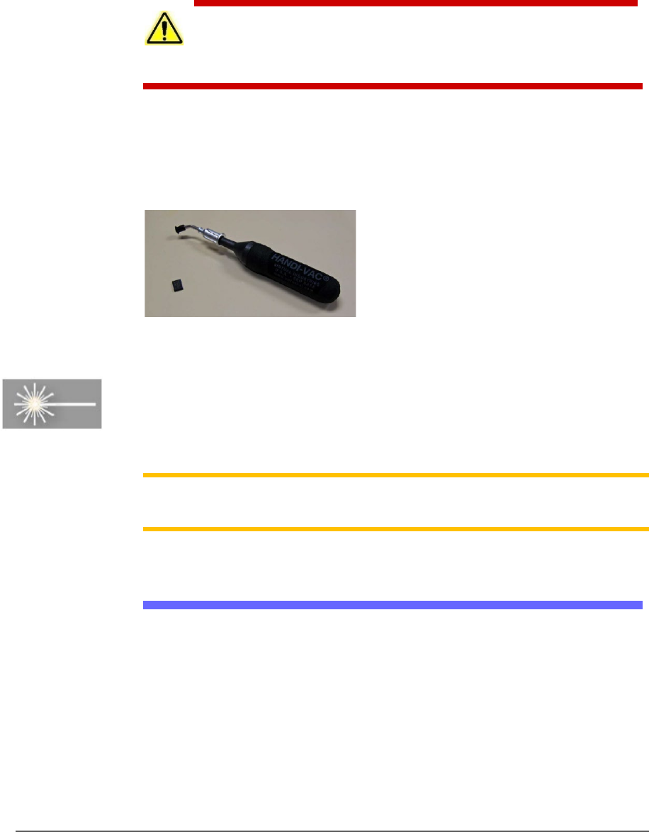
To prevent damage to device pins, use a vacuum tool, also called a
vacuum tweezer, to pick up devices. The vacuum tool is designed to
handle devices without damaging them.
CAUTION: Possible device pin damage! Do not touch devices with your
hands or any implement other than the vacuum tool. Doing so could
damage devices with fine-pitched leads.
To pick up a device using the vacuum tools use a squeezable air bladder
for suction. There are a variety of models, sizes and tips. Some tips are
replaceable.
Figure 4: A Vacuum Tweezer, Data I/O PN 565-8000-001.
[LASER MARKING ONLY] FUME EXTRACTOR
Used with the Laser Marking option, the laser fume extractor removes
harmful smoke and hazardous materials from the marking area and
safely stores them for proper disposal.
Note: Refer to Laser Safety on page 27
for more information. For
maintenance, see Laser Marking Fume Extractor on page 126.
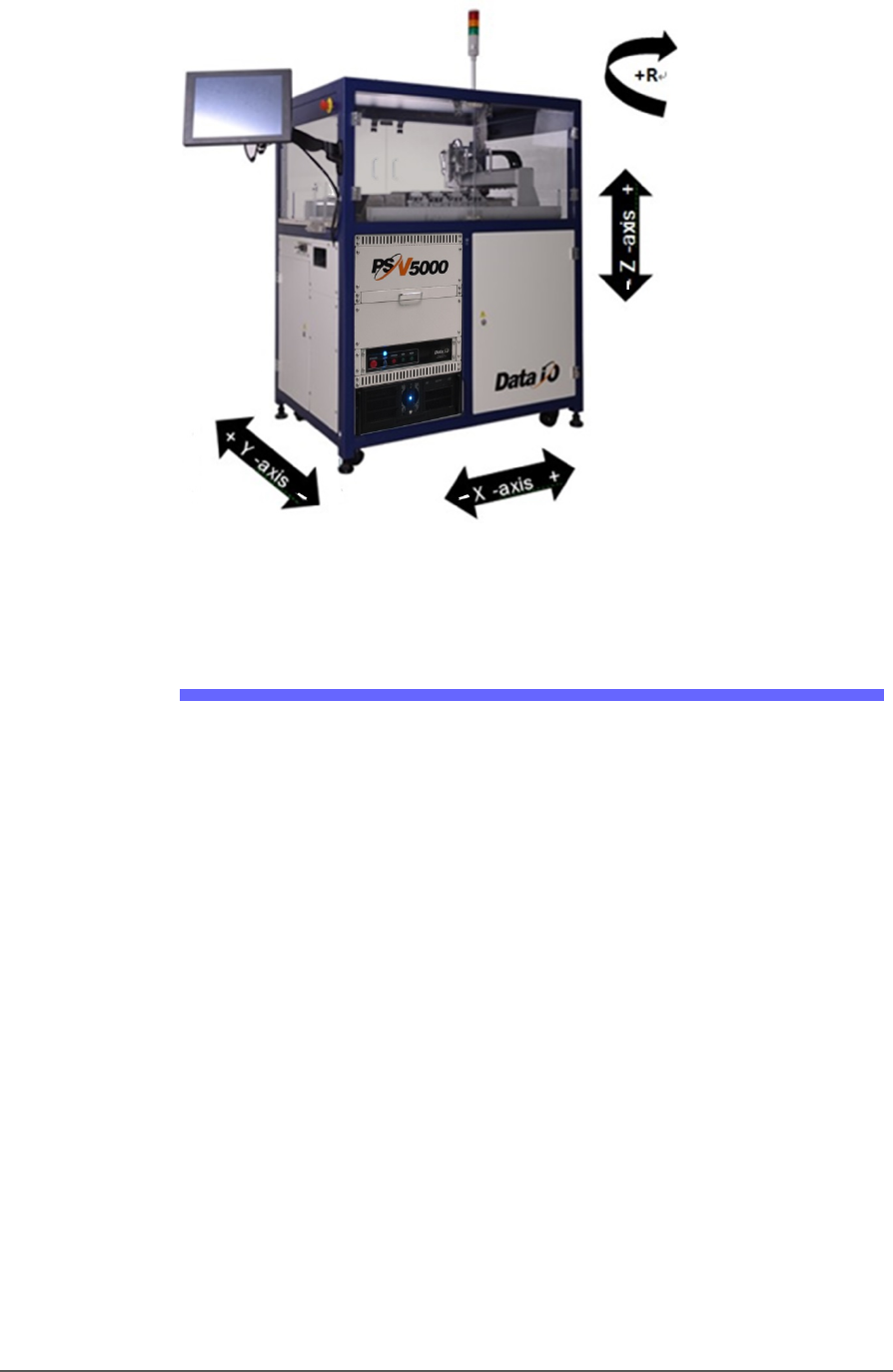
Machine Axes
The PSV5000 System gantry operates on three primary axes: X, Y, Z. An
additional axis, called the R-axis (theta), is used by the PNP head to
change device orientation (rotation).
■ System Description □ Basic Machine Functions
PSV5000 Owner’s Manual - 15 -
Figure 5: These axes describe motion direction on the PSV5000.
The X-Y coordinate 0, 0 is at the left front corner.
Basic Machine Functions
The PSV5000 System combines a device programming system and a
high-speed pick and place head (PNP head) to provide rapid
programming of standard pitch devices, as well as ultra-fine pitched
devices.
TaskLink™, or Job Creator or Job Runner software, and Automated
Handler software (CH700) running on the system’s Handler Computer
direct the PSV5000 System to perform a series of processes, including
automatic handling, programming, marking, and placement of devices
to the output media of your choice.
The PSV5000 System performs these basic operations when processing
devices:
1. Pick devices from the input media—
The pick and place head (PNP head) unloads devices from the input tube,
tray, or tape module. These devices are placed into programming sockets
in all cases except when Ignore Programmers is selected, in which case the
head takes devices directly to a different media (repackaging only) or to
the shuttle for marking only.
2. Process devices—

Introduction ■ System Description
- 16 - Data I/O ■ 096-0465-001C
Devices in the programming sockets undergo any or all of the following
processes as determined by the job. These processes are set in TaskLink:
• Continuity check
• ID check
• Erase
• Blank check
• Program
• Verify programming
• Read
• Illegal-bit check
• Functional verification operations
• Secure device
• Verify options such as voltage
(Optional) Mark devices—
When available, devices that pass the programming and verification
operations are marked at the Laser Module for identification.
3. Load devices into the output media—
Devices are moved by the PNP head to output media: trays, tubes, or
tape. Devices that fail one of the programming processes are placed into
the reject bin or reject tray.
Input and Output Options
PSV5000 System input and output options are: static tray (manual), tray
feeder (automatic), tube, and tape.
Most combinations of input and output options may be used. For
example, the PSV5000 System can be configured with input as static
tray and output as taped.
Manuals for Optional Equipment
The manuals that came with any optional equipment on your system
contain additional, more in-depth information. Some of the manuals
came in hard copy format with your PSV5000 System. Others are PDFs
installed on the Handler computer.