PSV5000_OwnersManual.pdf - 第23页
■ Machine Co mpo nents □ Sa f ety Sys t ems PSV5000 O wner ’s M anual - 19 - Mac hine C ompone nts The PSV50 00 System ha s many component s, or subas semblies, t hat work togeth er. Refe r to the figure belo w to lo cat…

Introduction ■ System Description
- 18 - Data I/O ■ 096-0465-001C
PSV5000 Specifications
Specifications are without optional equipment.
FACILITIES
Supply Air Pressure clean, dry, oil‐free air at
5.5–
8.2 Bar (551–827 kilopascals)
(80–120 PSI)
Air Flow 85 liters/minute (3 CFM)
maximum air flow
AC Input Voltage 208–240 VAC, single phase
AC Input Frequency 50–60 Hz
AC Input Power (max) 15 Amps (with all options)
PSV5000 DIMENSIONS
Length, x-axis (including
monitor)
1
130 cm (51 inches)
Width (including monitor)
1
87 cm (34 inches)
Height: machine (doors closed)
then add [light tower]
153 cm (62 inches) +
[56 cm, 22 in.]
Weight (no optional
equipment), approximate
450 kg (1000 lbs.)
Environment
Operating Temperature
Hours required for
temperature stabilization
+13° to +32° C (+55° to +90° F)
8 hours after transportation
Relative Humidity 35% to 90% non‐condensing
Sound level 75 dB or less
OTHER
Handler PC Operating System Windows 7 OS, 32-bit
Monitor 15 inch TFT Touchscreen
1
Since the monitor arm rotates, length and width dimensions can be
adjusted
inversely, up to 10 cm (4 inches). For example, if you sub‐
tract 10 cm from
length, then add 10 cm to width.
■ Machine Components □ Safety Systems
PSV5000 Owner’s Manual - 19 -
Machine Components
The PSV5000 System has many components, or subassemblies, that
work together. Refer to the figure below to locate primary components.
Safety Systems
LIGHT TOWER
Allows monitoring the status of the PSV5000 System from a distance
while the system is processing devices. See Light Tower Interpretation in
the Operator’s Manual for a complete description of lamp colors and
significance.
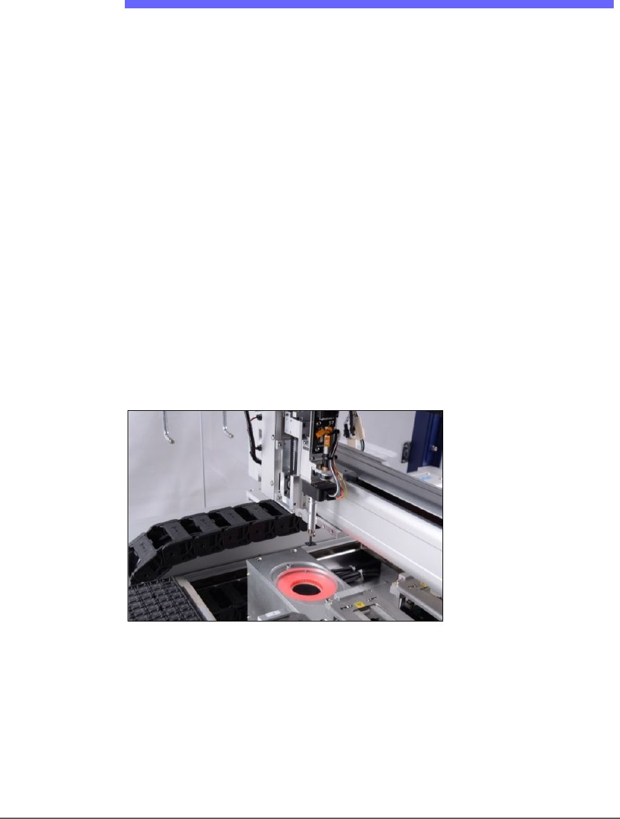
GANTRY
Travels along X- and Y-axes moving the PNP head to different locations
within the work envelope. It moves devices in four axes,
X, Y, Z, and R.
The PNP head uses different sized probe tips to accommodate the great
number of device types that are available. See Installing the Correct Probe
in the Operator’s Manual. During operation, vacuum at each probe holds
a device. Vacuum sensors detect whether or not a device is present on a
probe tip.
Figure 7: The PSV5000 PNP head.
The probe picks up a device and moves it to a programming socket. To
place devices at target locations, a probe lowers, vacuum is turned off
and blow-off air is momentarily turned on.
Introduction ■ Machine Components
- 20 - Data I/O ■ 096-0465-001C
WARNING: Collision hazard! The gantry system and associated
components move with high speed and force, and have the
potential to cause great bodily harm. Do not bypass the safety
interlocks or operate the with the safety doors open or removed.
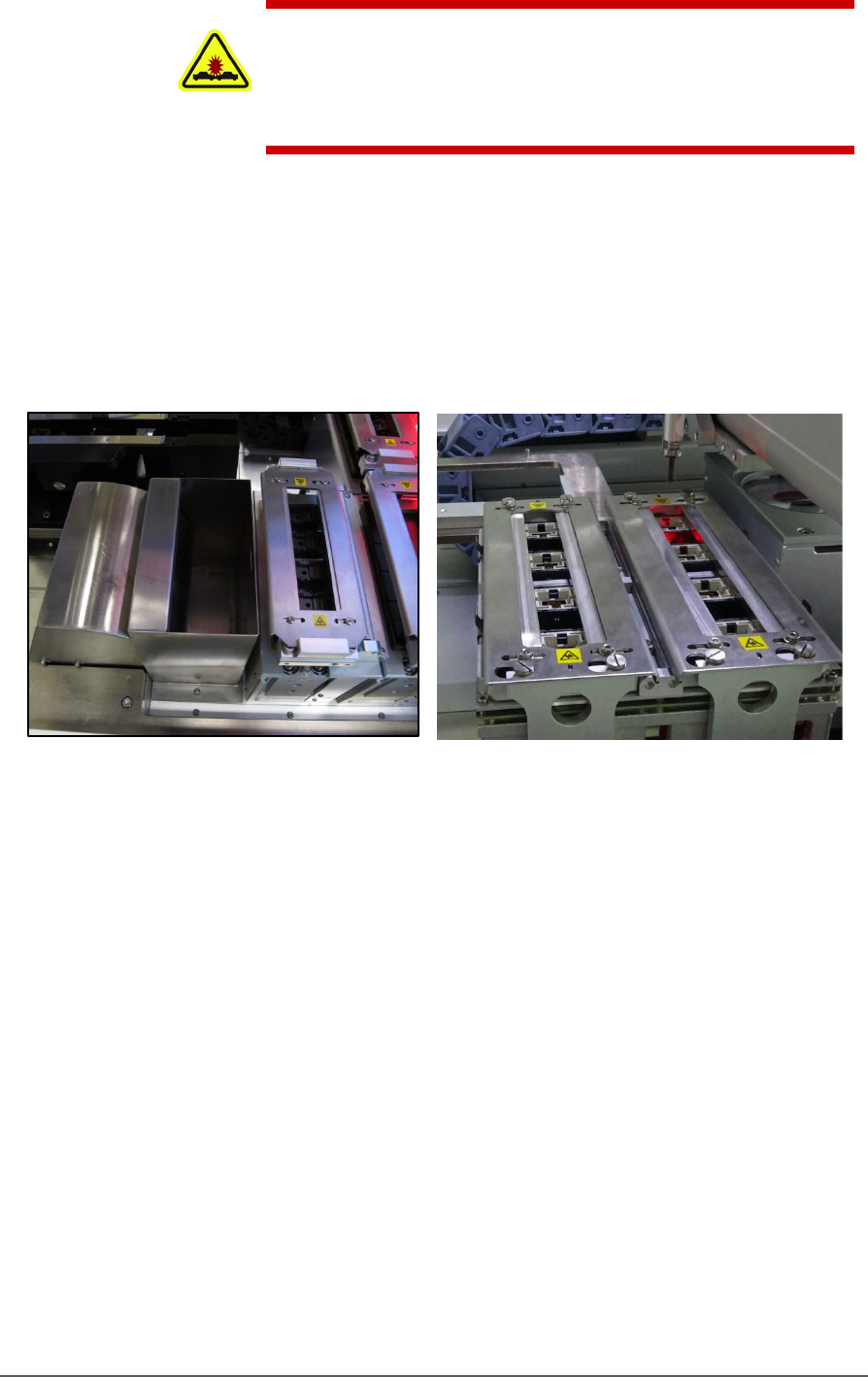
PROGRAMMERS
Data I/O’s FlashCORE III programming modules are used in many
Data I/O products and have most algorithm support. LumenX
programmers are one of the fastest programmer architectures currently
available. Programmer Modules in the PSV5000 include pneumatic
socket actuation.
Figure 8: Left: A FlashCORE Programmer (next to the reject bin),
and Right: a LumenX Programmer.
VISION SYSTEM
PSV5000 uses an upward camera for precise picking and placing.
STATIC TRAY MOUNT
Using positioning pins and a magnetic bracket, JEDEC and non-JEDEC
standard trays are held firm for the PNP head to pick devices and return
them after processing.