PSV5000_OwnersManual.pdf - 第24页
Introduction ■ Machine Compo ne nts - 20 - Data I/O ■ 096 - 0465 - 00 1C WAR NING: Co llisio n haza rd! The gan try syst em and as sociat ed compon ents move with high speed and for ce, and have the poten tial t o caus e…
■ Machine Components □ Safety Systems
PSV5000 Owner’s Manual - 19 -
Machine Components
The PSV5000 System has many components, or subassemblies, that
work together. Refer to the figure below to locate primary components.
Safety Systems
LIGHT TOWER
Allows monitoring the status of the PSV5000 System from a distance
while the system is processing devices. See Light Tower Interpretation in
the Operator’s Manual for a complete description of lamp colors and
significance.
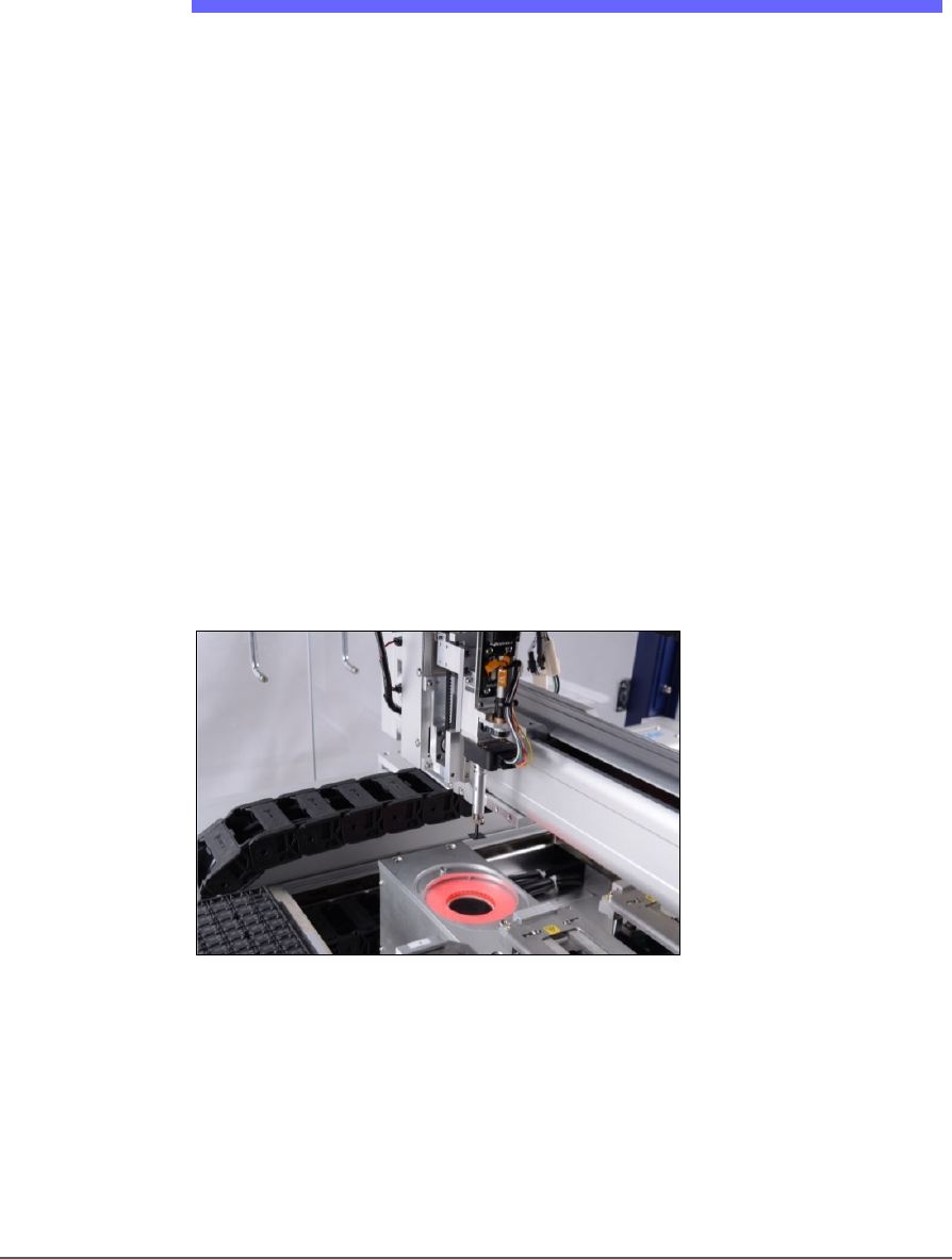
GANTRY
Travels along X- and Y-axes moving the PNP head to different locations
within the work envelope. It moves devices in four axes,
X, Y, Z, and R.
The PNP head uses different sized probe tips to accommodate the great
number of device types that are available. See Installing the Correct Probe
in the Operator’s Manual. During operation, vacuum at each probe holds
a device. Vacuum sensors detect whether or not a device is present on a
probe tip.
Figure 7: The PSV5000 PNP head.
The probe picks up a device and moves it to a programming socket. To
place devices at target locations, a probe lowers, vacuum is turned off
and blow-off air is momentarily turned on.
Introduction ■ Machine Components
- 20 - Data I/O ■ 096-0465-001C
WARNING: Collision hazard! The gantry system and associated
components move with high speed and force, and have the
potential to cause great bodily harm. Do not bypass the safety
interlocks or operate the with the safety doors open or removed.
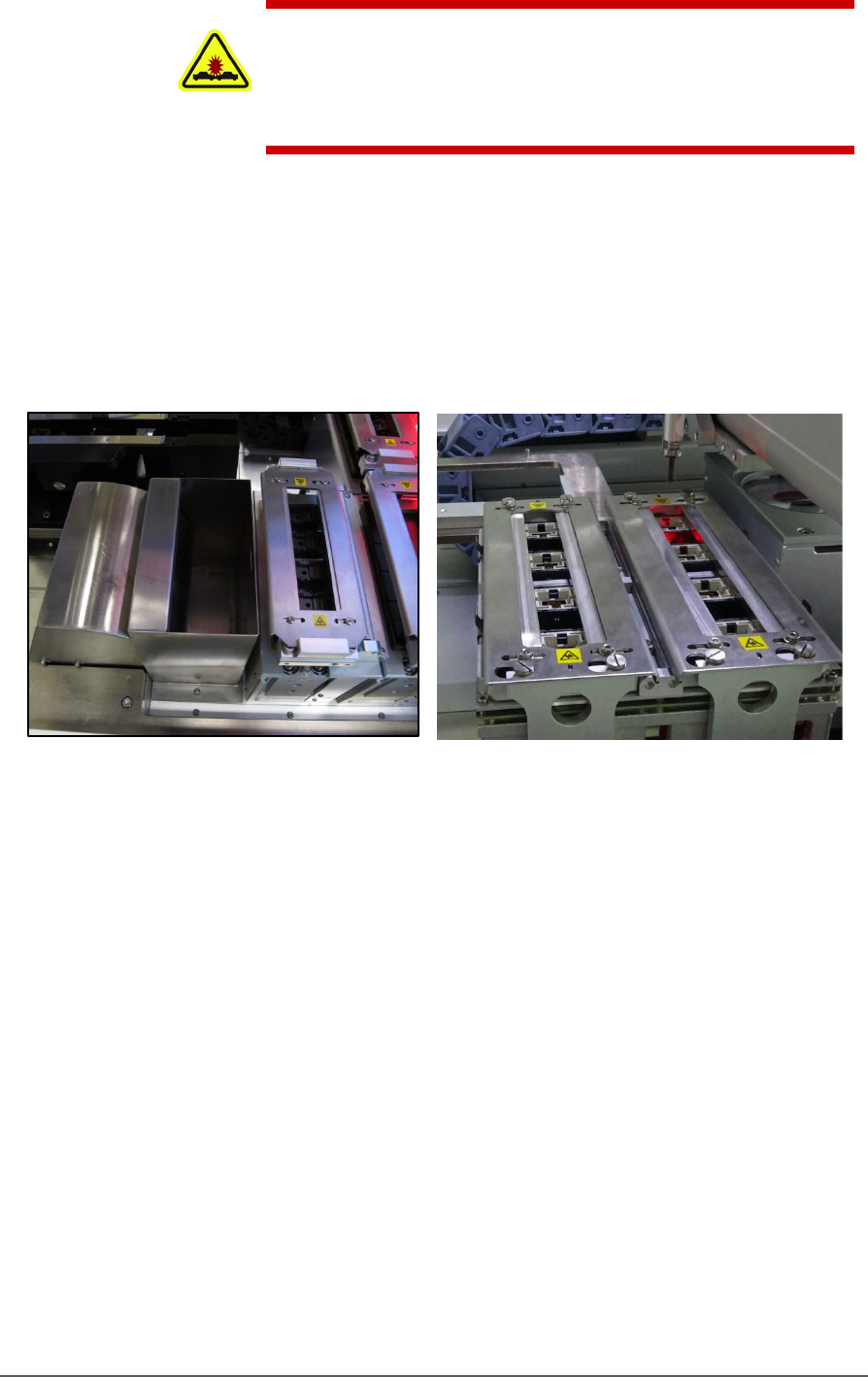
PROGRAMMERS
Data I/O’s FlashCORE III programming modules are used in many
Data I/O products and have most algorithm support. LumenX
programmers are one of the fastest programmer architectures currently
available. Programmer Modules in the PSV5000 include pneumatic
socket actuation.
Figure 8: Left: A FlashCORE Programmer (next to the reject bin),
and Right: a LumenX Programmer.
VISION SYSTEM
PSV5000 uses an upward camera for precise picking and placing.
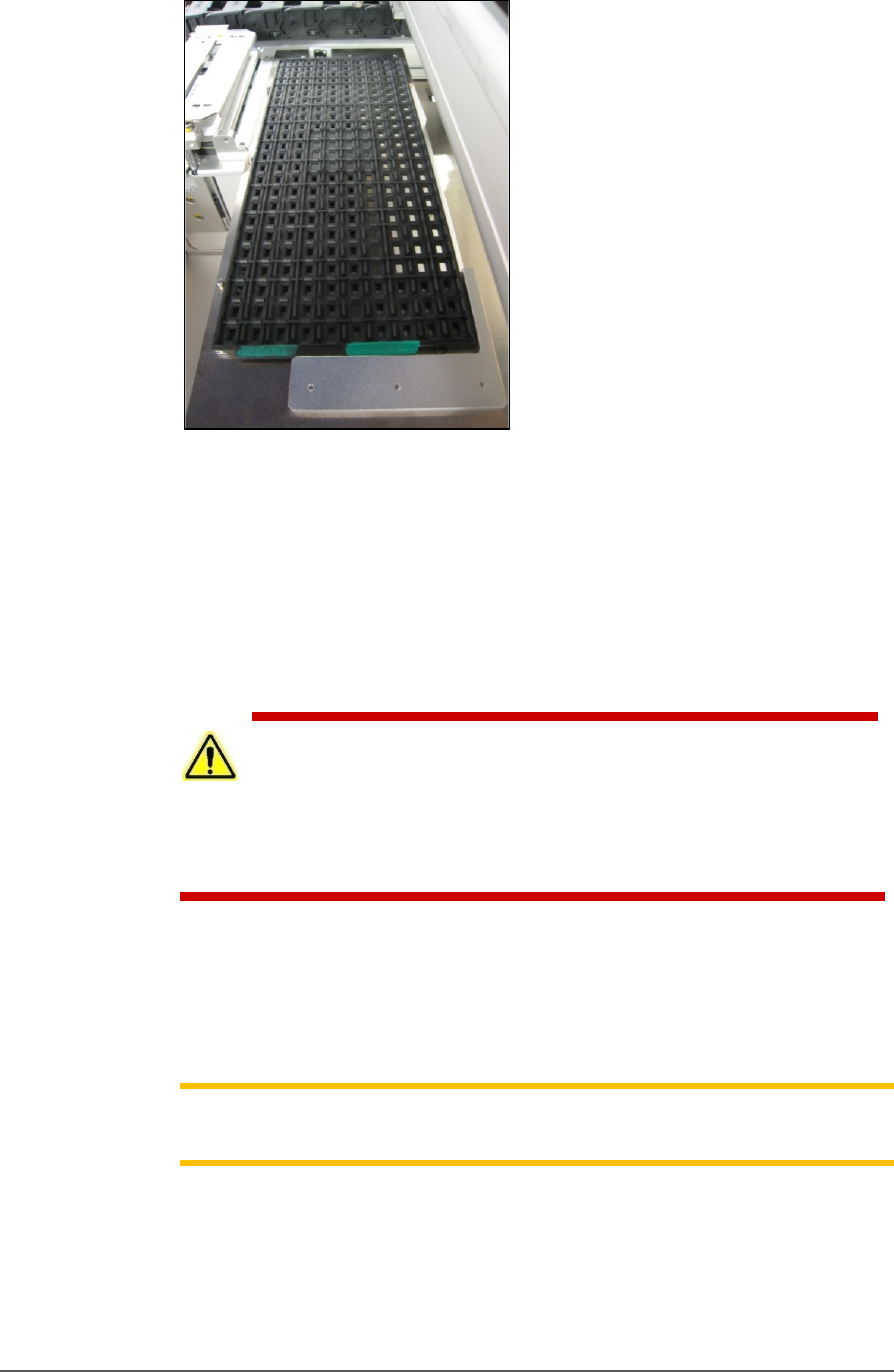
STATIC TRAY MOUNT
Using positioning pins and a magnetic bracket, JEDEC and non-JEDEC
standard trays are held firm for the PNP head to pick devices and return
them after processing.
■ Machine Components □ Safety Systems
PSV5000 Owner’s Manual - 21 -
Figure 9: A typical Static tray installation. Note that the beveled
corner is at the far left, adjacent to the sensor.
HANDLER COMPUTER
The on-board Handler computer hosts TaskLink software and the
CH700 software, and monitors all sensors. The computer contains a
CPU that runs Microsoft Windows 7 Operating System (at time of
release).
CAUTION: Possible machine damage! Adding software to the PSV5000
System can cause damage or cause the system to operate improperly.
Adding software without specific instruction from Data I/O Customer Support
will void the warranty and may incur service charges if subsequent service is
required.
KEYBOARD AND TOUCH SCREEN
Both methods of input are available for operation. With the touchscreen,
tap the screen with a finger only, not sharp objects such as pens or
pencils.
Note: Throughout this Owner’s Manual, the term click is also used to
mean tap when using the touch screen monitor.
ESD STRAP CONNECTION
When operators plug an antistatic wrist strap into the ESD strap
connection, it reduces the risk of damage to devices and Socket Adapters
from electrostatic discharge (ESD).