PSV5000_OwnersManual.pdf - 第25页
■ Machine Co mpo nents □ Sa f ety Sys t ems PSV5000 O wner ’s M anual - 21 - Figure 9: A ty pical Stati c tray in s tal lation . N ote that th e beveled co rner is at th e far left, a dja cen t to th e sen sor. H ANDLE R…
Introduction ■ Machine Components
- 20 - Data I/O ■ 096-0465-001C
WARNING: Collision hazard! The gantry system and associated
components move with high speed and force, and have the
potential to cause great bodily harm. Do not bypass the safety
interlocks or operate the with the safety doors open or removed.
PROGRAMMERS
Data I/O’s FlashCORE III programming modules are used in many
Data I/O products and have most algorithm support. LumenX
programmers are one of the fastest programmer architectures currently
available. Programmer Modules in the PSV5000 include pneumatic
socket actuation.
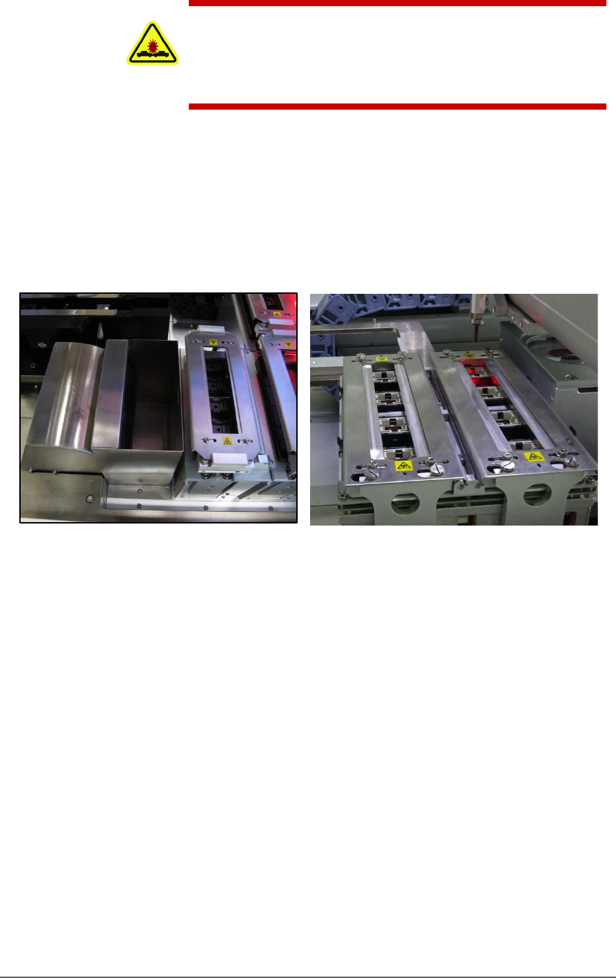
Figure 8: Left: A FlashCORE Programmer (next to the reject bin),
and Right: a LumenX Programmer.
VISION SYSTEM
PSV5000 uses an upward camera for precise picking and placing.
STATIC TRAY MOUNT
Using positioning pins and a magnetic bracket, JEDEC and non-JEDEC
standard trays are held firm for the PNP head to pick devices and return
them after processing.
■ Machine Components □ Safety Systems
PSV5000 Owner’s Manual - 21 -
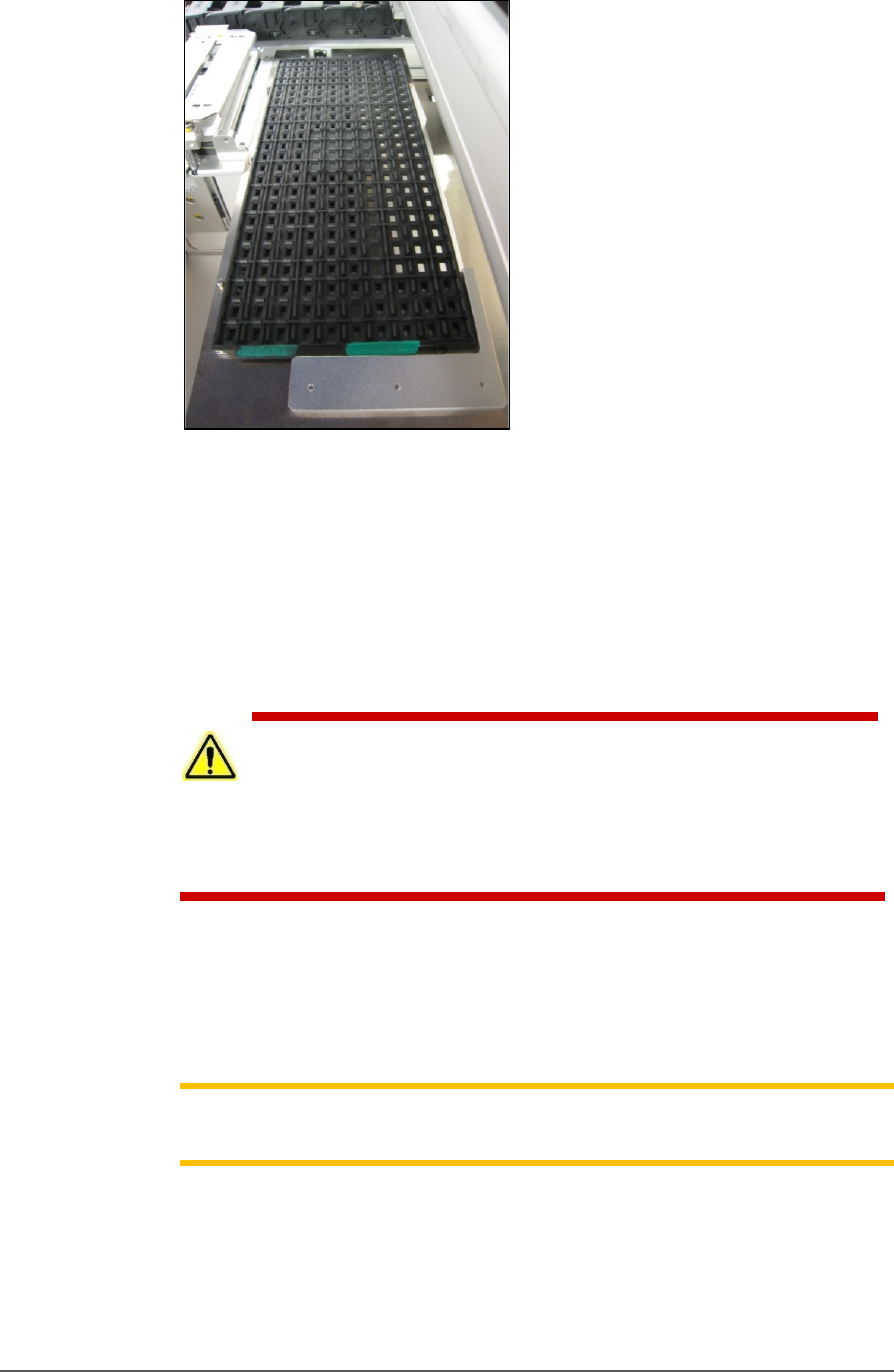
Figure 9: A typical Static tray installation. Note that the beveled
corner is at the far left, adjacent to the sensor.
HANDLER COMPUTER
The on-board Handler computer hosts TaskLink software and the
CH700 software, and monitors all sensors. The computer contains a
CPU that runs Microsoft Windows 7 Operating System (at time of
release).
CAUTION: Possible machine damage! Adding software to the PSV5000
System can cause damage or cause the system to operate improperly.
Adding software without specific instruction from Data I/O Customer Support
will void the warranty and may incur service charges if subsequent service is
required.
KEYBOARD AND TOUCH SCREEN
Both methods of input are available for operation. With the touchscreen,
tap the screen with a finger only, not sharp objects such as pens or
pencils.
Note: Throughout this Owner’s Manual, the term click is also used to
mean tap when using the touch screen monitor.
ESD STRAP CONNECTION
When operators plug an antistatic wrist strap into the ESD strap
connection, it reduces the risk of damage to devices and Socket Adapters
from electrostatic discharge (ESD).
Introduction ■ Machine Components
- 22 - Data I/O ■ 096-0465-001C
SAFETY DOORS
Designed to protect against injury and damage from the PNP head
movement, the safety doors are an important safety feature, stopping the
gantry when they are opened.
For more information see Safety Door with Interlocks on page 22.
POWER PANEL
The Power Panel is on the lower left side of the machine.
CONNECTIONS
The Power Panel allows for the attachment of AC power and air.
Optional connections:
You can connect an Ethernet cable for internet connection
CONTROLS
Mounted on the Power Panel are the main power switch and the main air
regulator and filter. There is a second regulator with a separate gauge for
adjusting socket opener pressure. See Adjusting the Socket Actuator Air
Pressure on the Programmers on page 99.
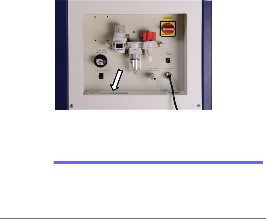
Figure 10: Power Panel (Facilities Panel) on the back of the machine.
The Serial Number is there, also (arrow).
Optional Equipment Descriptions
CIRCUIT BREAKERS
There is a toggle switch on the power panel which allows shutting off
power to only the programmers.