PSV5000_OwnersManual.pdf - 第27页
■ Machine Co mpo nents □ Optional Equipment Desc riptions PSV5000 O wner ’s M anual - 23 - Numerous har dware opti ons can be purch ased with PSV5000 , most of which are t he vario us in put a nd outpu t mode s. The non …
Introduction ■ Machine Components
- 22 - Data I/O ■ 096-0465-001C
SAFETY DOORS
Designed to protect against injury and damage from the PNP head
movement, the safety doors are an important safety feature, stopping the
gantry when they are opened.
For more information see Safety Door with Interlocks on page 22.
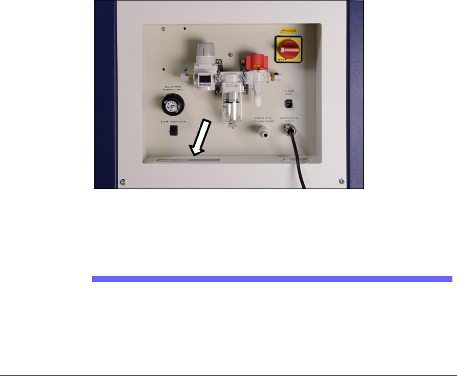
POWER PANEL
The Power Panel is on the lower left side of the machine.
CONNECTIONS
The Power Panel allows for the attachment of AC power and air.
Optional connections:
You can connect an Ethernet cable for internet connection
CONTROLS
Mounted on the Power Panel are the main power switch and the main air
regulator and filter. There is a second regulator with a separate gauge for
adjusting socket opener pressure. See Adjusting the Socket Actuator Air
Pressure on the Programmers on page 99.
Figure 10: Power Panel (Facilities Panel) on the back of the machine.
The Serial Number is there, also (arrow).
Optional Equipment Descriptions
CIRCUIT BREAKERS
There is a toggle switch on the power panel which allows shutting off
power to only the programmers.
■ Machine Components □ Optional Equipment Descriptions
PSV5000 Owner’s Manual - 23 -
Numerous hardware options can be purchased with PSV5000, most of
which are the various input and output modes. The non-input/output
option is laser marking for devices.
LASER MARKING DEVICES
The Laser Marking System uses a compact Laser to mark devices. The
laser applies a customer-defined mark. MarkingMate is supplied with
the laser for creating marking files. The laser marking system operates
as a Class 1 laser system, with a class 4 embedded laser (CDRH
classification), and therefore uses integrated interlocks to prevent the
laser from firing while any cover is open. The laser should never be
operated without safety covers in place. Observe all warnings regarding
laser usage.
For additional safety information, see Laser Safety on page 27.
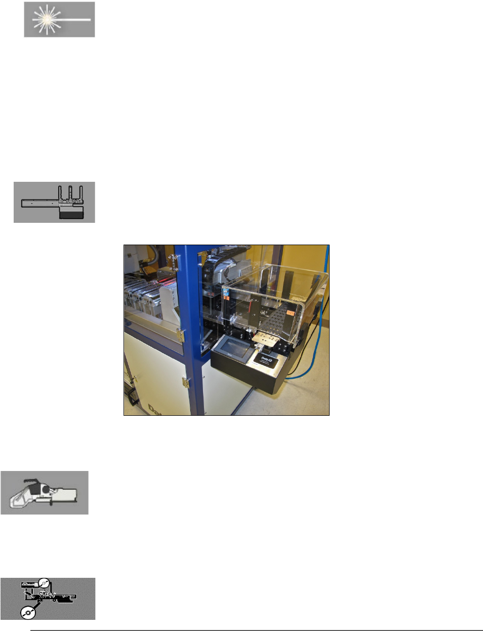
(OPTIONAL) AUTOMATIC TRAY FEEDER
Designed to automatically supply trays full of devices to the PSV5000
System, the Tray Feeder CB accepts up to twenty thin or thick JEDEC
trays.
Figure 11: The Tray Feeder.
(Optional) Tape Input Module
The tape input module is a mount and communication accommodating
a chip feeder which provides devices for programming. Use the
appropriate size tape width/feeder. Each device is picked from a carrier
tape pocket and placed into a programming socket.
(Optional) Tape Output Module
The tape output module, mounts onto the left side of the machine and
uses a reel of empty carrier tape to hold devices after they are
programmed. It supports all widths. Programmed devices are placed into

Introduction ■ Machine Components
- 24 - Data I/O ■ 096-0465-001C
empty pockets on the carrier tape. The carrier tape advances through
either a heat seal or pressure seal unit that applies cover tape to the
carrier tape.