PSV5000_OwnersManual.pdf - 第35页
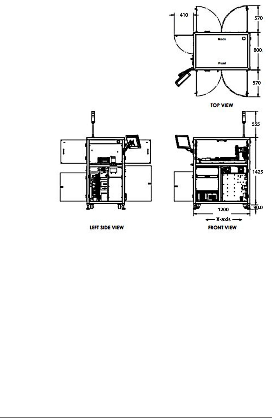
■ Room Consideratio n □ Acce ss Space PSV5000 O wner ’s M anual - 31 - Figure 15: Max imum envel ope of PSV5000 wit hout optio nal equipme nt such as m arking, Ta pe - In or Tape Outpu t Modules. ( Dimensi ons in mm. Red…
Introduction ■ Room Consideration
- 30 - Data I/O ■ 096-0465-001C
THE INTENDED AREA FOR INSTALLATION MUST:
• allow at least one meter (39 inches) of clearance on all sides of the
machine for opening access panels as well as repairing and
replacing subassemblies,
• provide a solid foundation (for example, a concrete floor). The
machine contains a fast-moving gantry with much mass. The area
for it must be stable, solid, and mostly level prior to installation. If
this is not achievable, consider installing the system at another
location.
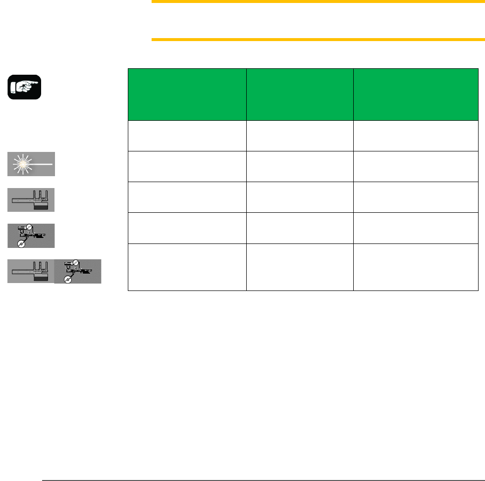
The table below lists recommended, minimum envelope size
determined by the 1 meter access space required on each side:
MINIMUM PHYSICAL ENVELOPE
Note: The numbers below do not include ventilation requirements
discussed in the previous heading Ventilation.
Machine
Configuration
Width x Depth
(X-axis x Y-axis)
Width x Depth
+ 1 m all sides
for access
PSV5000 Only 1.5 m x 0.87 m 3.5 m x 2.87m
PSV5000 + Laser 1.3 m x 0.87 m 3.2 m x 2.87m
PSV5000 + Tray Feeder
2.1 m x 0.87 m 4.1 m x 2.87 m
PSV5000 + Tape Out
Module with Large reel
2.2 m x 0.87 m 4.2 m x 2.87 m
PSV5000 + Tray Feeder
+ Tape Out Module with
Large reel
2.9 m x 0.87m 4.9 m x2 .87m
For example, a PSV5000 System with a Tray Feeder requires a
minimum physical area of 4.1 meters wide x 2.87 meters deep for
easy access.
■ Room Consideration □ Access Space
PSV5000 Owner’s Manual - 31 -
Figure 15: Maximum envelope of PSV5000 without optional
equipment such as marking, Tape-In or Tape Output Modules.
(Dimensions in mm. Reduced scale).