PSV5000_OwnersManual.pdf - 第46页
Setu p ■ S etting Up In put and Output Media - 42 - Data I/O ■ 096 - 0465 - 00 1C Figure 19: Commo n loc atio ns fo r th e rej ect tr ay and bin wi th Tap e Input and Tape Output . O nly one is n ecessary. The reject b i…
■ Setting Up Input and Output Media □ Install the Reject Bin
PSV5000 Owner’s Manual - 41 -
REQUIREMENTS
Metric hex key set.
To remove a Static Tray Platform:
1. Shut OFF the PSV5000 System. See Shutting Down the PSV5000
System on page 38.
2. Disconnect the tray sensor-
2a. Remove two sensor bracket screws (2.5 mm).
2b. Lift the bracket up and remove the two screws securing the
sensor to the bracket (1.5 mm).
Note: Best practice is to re-attach the sensor screws to the bracket, and
the bracket to the platform so parts don’t get lost.
3. Open the front or back lower access door and remove four screws
from the target Static Tray Platform (3 mm hex key).
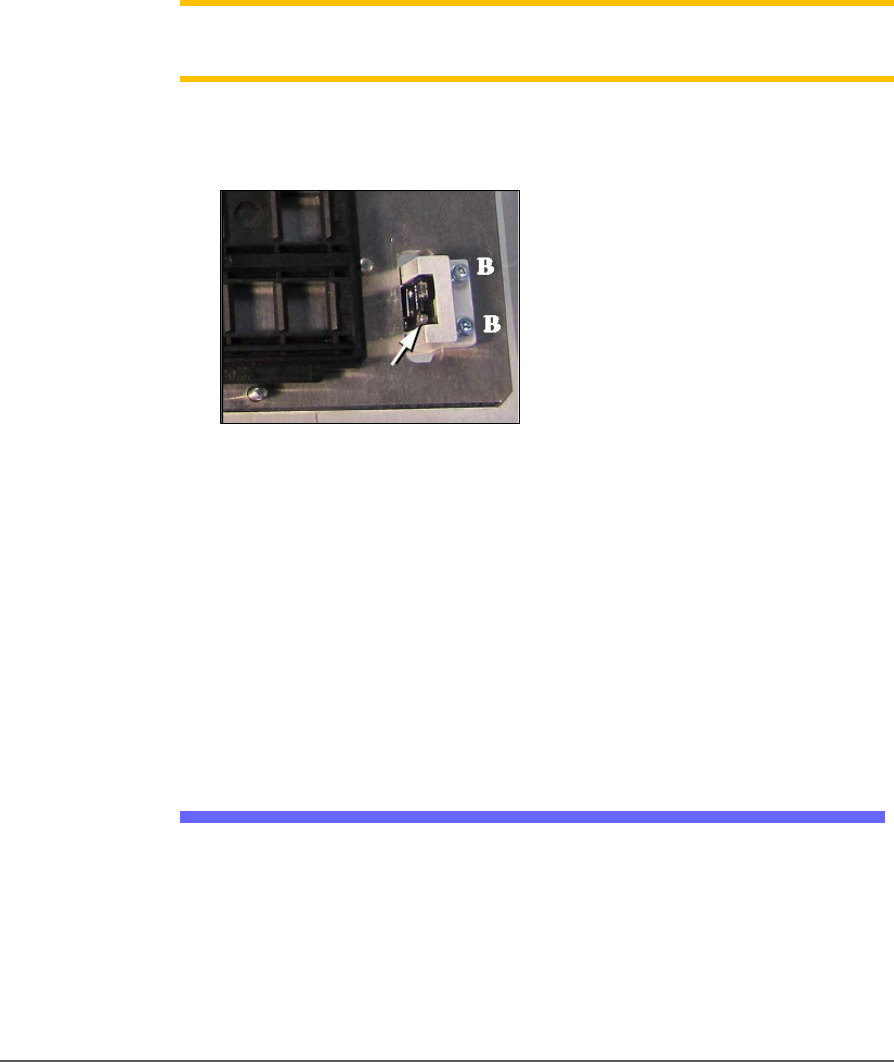
Figure 18: Static Tray Sensor and bracket. Two bracket screws
shown (at B). Only one of the sensor screws is visible (arrow).
(This image is for reference only. Yours may not be positioned
like this.)
4. Move the sensor into the bottom side of the machine through the
sensor cable hole in the working plate. Tie it carefully to the cable
way.
To re-install the platform, reverse the steps for removal.
Install the Reject Bin
Install a reject container for devices failing any process. Many workspace
layouts are possible. Generally, a reject bin (or box) is placed on the front
left of the workspace as shown in Figure 2-5, on top the Tape Input
media exit chute. However, a box or pad can be placed wherever there is
room for it as long as its location is taught in the Package File.
Setup ■ Setting Up Input and Output Media
- 42 - Data I/O ■ 096-0465-001C
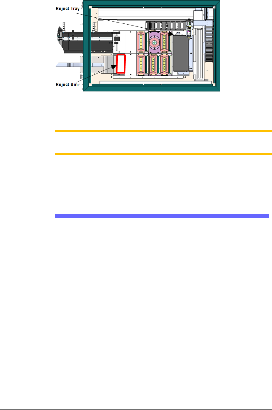
Figure 19: Common locations for the reject tray and bin with Tape
Input and Tape Output. Only one is necessary. The reject bin
that comes with the PSV5000 should be placed as shown.
Note: On the Gantry window, the reject bin or tray is associated with a
yellow position label that reads RTr.
The reject bin just lifts in and out by hand.
A tray may be used as a reject container instead of a bin.
Auxiliary Tray
If a reject tray and an auxiliary tray is used as shown below, the
mounting plate for the Tape-In Module must be removed as well as the
mounting bracket for the reject bin. Contact Data I/O Support for
instructions.
■ Setting Up Input and Output Media □ Setting Up an Automatic Tray Feeder
PSV5000 Owner’s Manual - 43 -
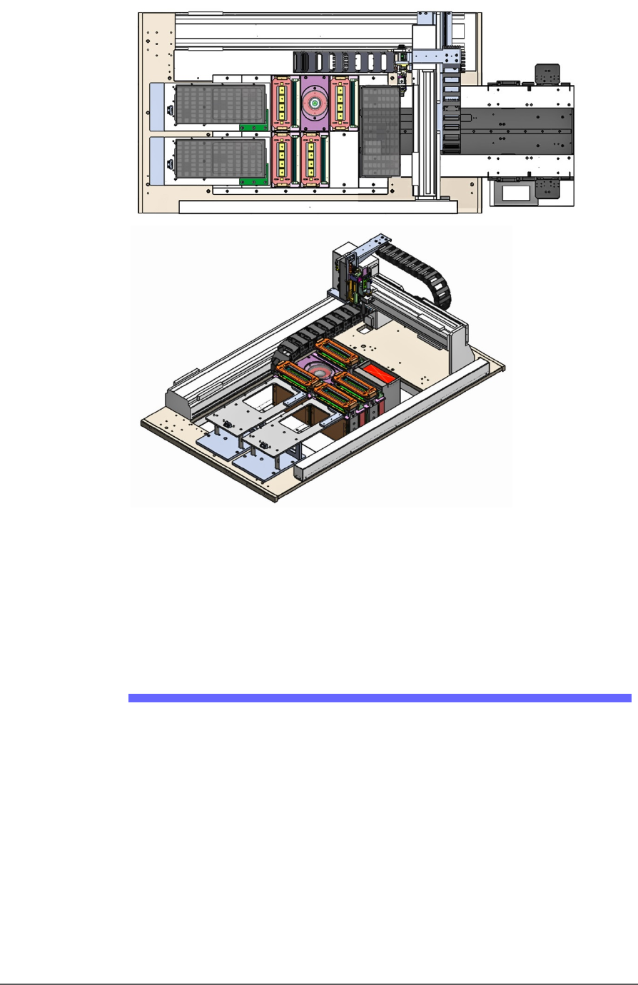
Figure 20: Two possible workspace configurations with trays on the
left. A reject tray and an auxiliary tray with Auto Tray Feeder
(top) and a Tray to Tray with a reject bin (trays not shown)
(bottom). Two tray mounts must be installed on the left for these
configurations.
Setting Up an Automatic Tray Feeder
The PSV5000 System can be configured with an Automatic Tray Feeder.
The Tray Feeder must be level to the Gantry and square to the PSV5000
Machine. For general information about setting it up, see the Tray
Feeder Owner’s Manual that came with your system. Look for the
heading Installation.