PSV5000_OwnersManual.pdf - 第49页
■ Setting Up Input and Output Media □ Setting Up an Automatic Tray Feeder PSV5000 O wner ’s M anual - 45 - Figure 22: The safety shiel d for th e Tray Feed er has been rotated out of the way and fa stened in t he ‘storag…
Setup ■ Setting Up Input and Output Media
- 44 - Data I/O ■ 096-0465-001C
Prior to editing the
winAH400.ini file, make
a backup copy.
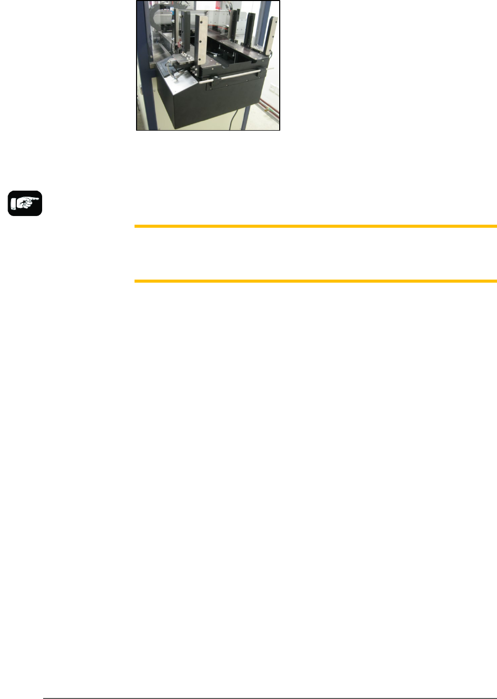
Figure 21: Tray Feeder mounted on PSV5000.
The winAH400.ini file requires editing prior to using a Tray Feeder if
your PSV5000 Machine has not already been set up for one at the factory.
See the CH700 on-screen Help file for topic Editing the winAH400.ini file.
Note: When your winAH400.ini file is set to run an Automatic Tray Feeder,
before you can run static trays again, the file will need to be changed back
to ModelTray1=STD.
INSTALLING THE TRAY FEEDER
The Tray Feeder can only be installed if your PSV5000 was set up for it at
the factory or by a Data I/O Service Technician.
REQUIREMENTS
•
Two people to lift it
•
Metric hex key set
•
Key to access door
To install the Tray Feeder:
1. Shut OFF PSV5000 power. See Shutting Down the PSV5000 System
on page 38.
2. Remove the Input and Output static tray mounts, if installed.
Refer to Removing Tray Platforms on page 40.
3. On the right side of the machine, locate the clear rectangular shield
covering the Tray Feeder opening and remove the left screw with a
4 mm hex key.
■ Setting Up Input and Output Media □ Setting Up an Automatic Tray Feeder
PSV5000 Owner’s Manual - 45 -
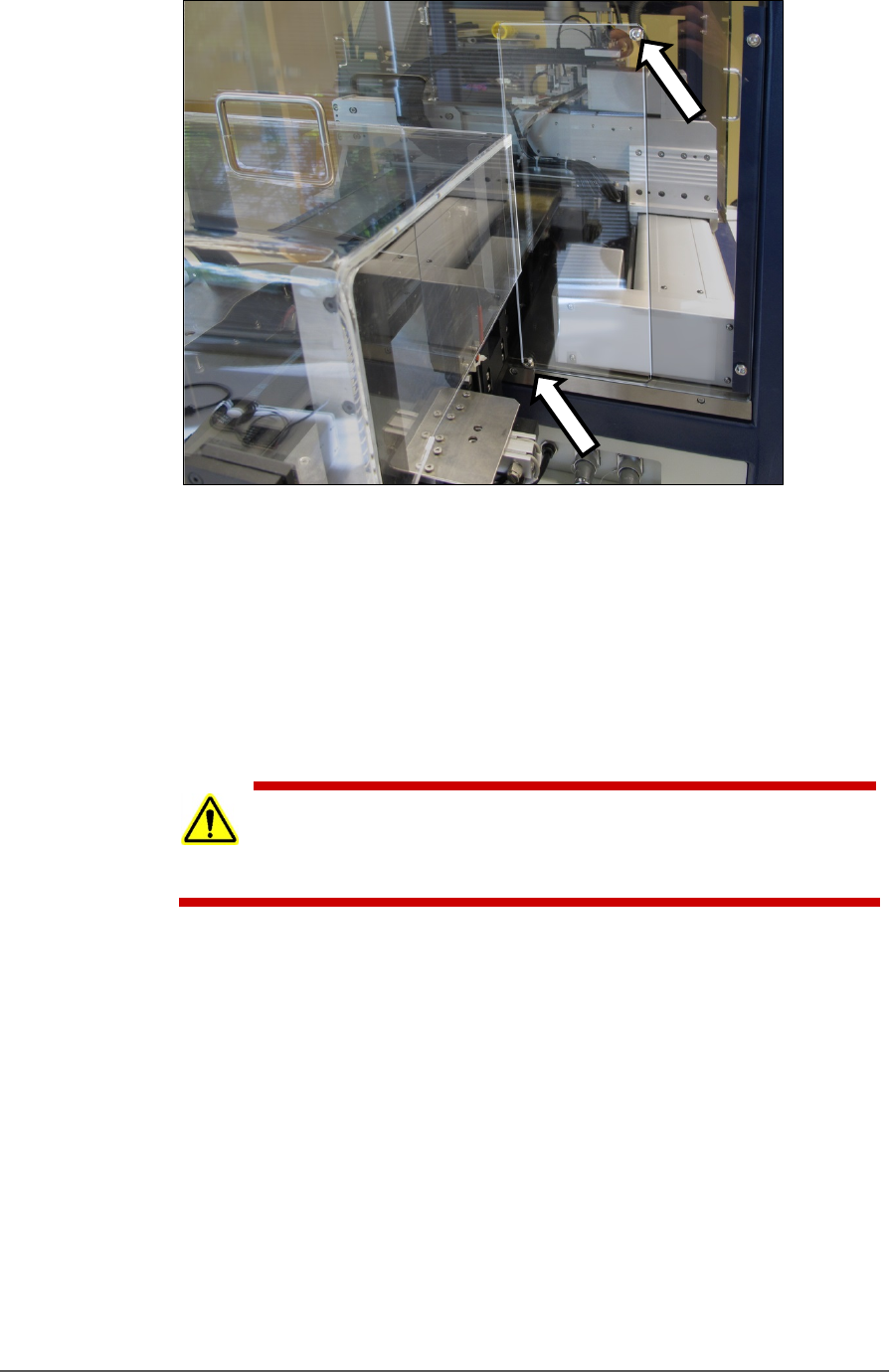
Figure 22: The safety shield for the Tray Feeder has been rotated
out of the way and fastened in the ‘storage’ position with the two
screws (arrows).
4. Loosen the lower right screw.
5. Rotate the shield up 90° clockwise and fasten in place at the extra
hole with the screw removed earlier.
6. Get the Tray Feeder fasteners ready, and a 5 mm hex key.
CAUTION: Heavy equipment! The Tray Feeder weighs 30 kg (66 lb.).
Two people are required to lift it. A third person is needed to attach
fasteners. Use caution.
7. With two people lifting the Tray Feeder, slide the nose into the shield
opening and far enough in to accommodate the mounting holes on
the machine base plate.
Setup ■ Setting Up Input and Output Media
- 46 - Data I/O ■ 096-0465-001C
Refer to the following
figure for Tray Feeder
connections.
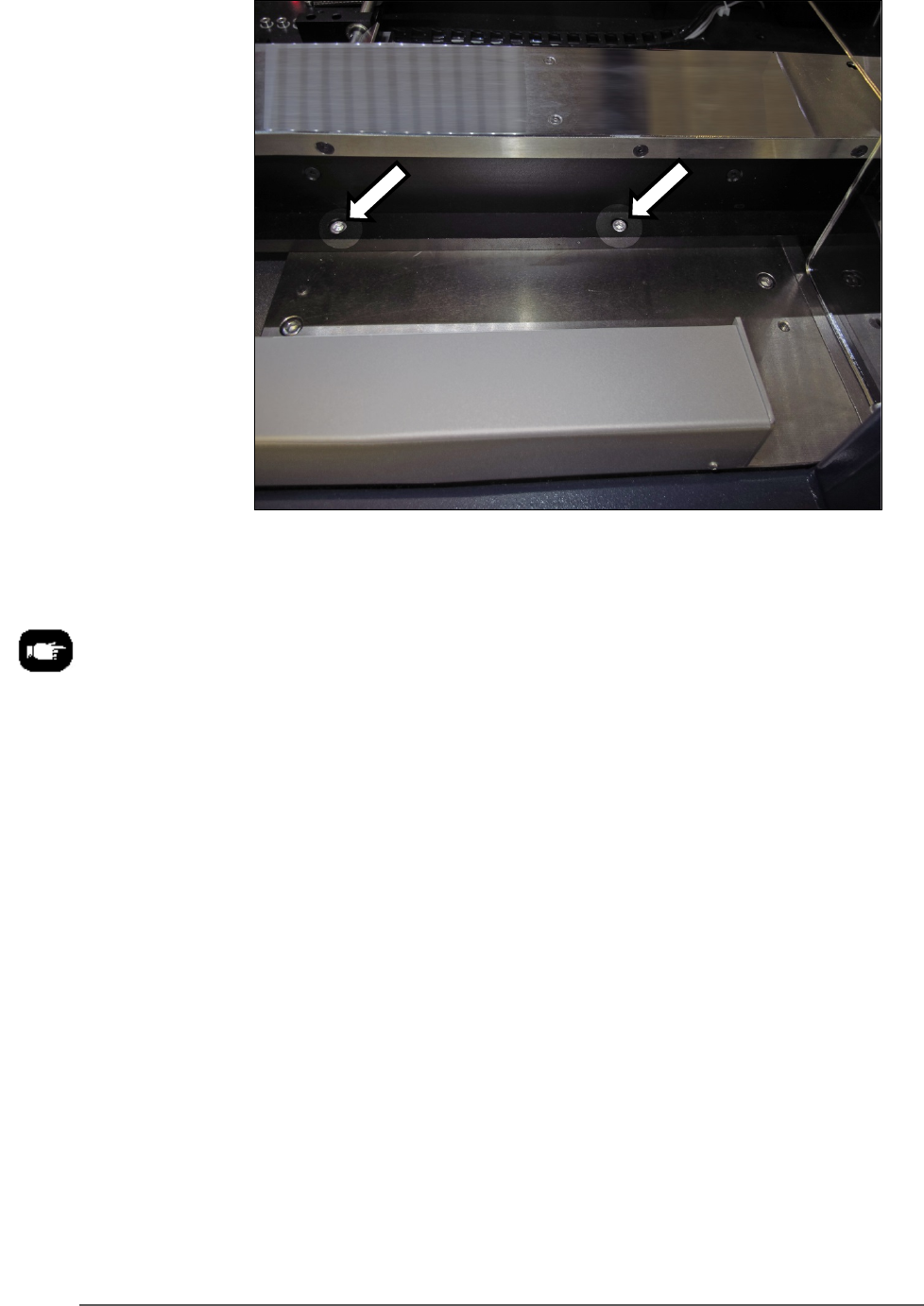
Figure 23: The Tray Feeder mounting screws (arrows). There are
also two fasteners on the back side of the feeder (not shown).
8. Screw in a screw into each of the four mounting holes to secure the
feeder (5 mm hex key).
9. Plug in the three utilities: air, electrical, signal cable.
The air connection has One-Touch fittings.
The electrical connector can be rotated until it slides into the socket,
and then screw the knurled ring up.